SimpleFOC stepstick

Branching this topic before it takes over the SimpleFOC-StepMini thread.

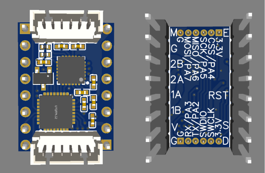
Yeah, I’d like to keep the cost as low as possible. That is helpful if we only need an encoder connector, but I may try for both anyway, or at least a 3 pin UART interface (RX, TX, GND) that can be connected while it’s plugged into the motherboard. It wouldn’t be too bad having to pull it out to flash the firmware, but I’d like to be able to configure the PID, KV, phase resistance, and other values while it’s powered by the printer so people don’t need to buy a standalone power supply to use it.

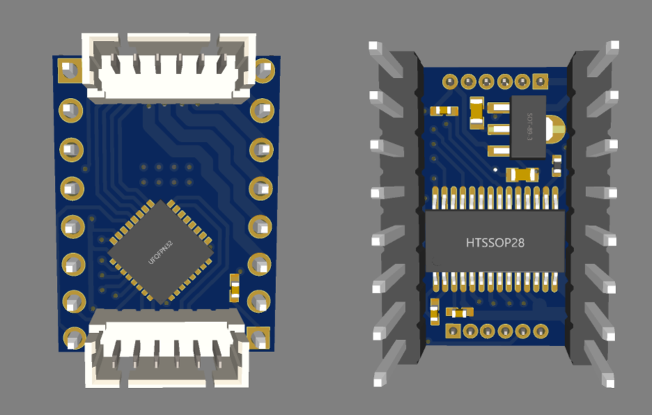
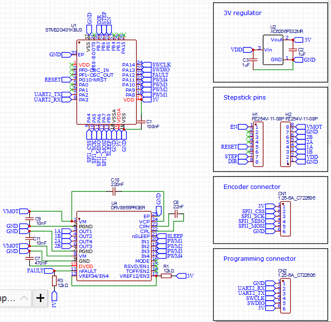
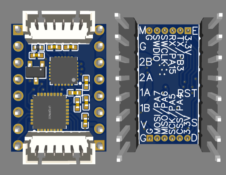
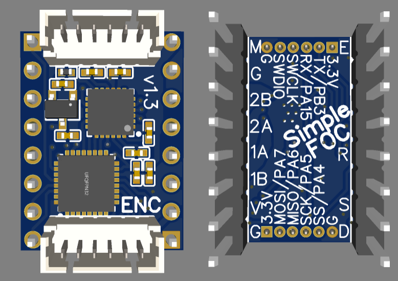
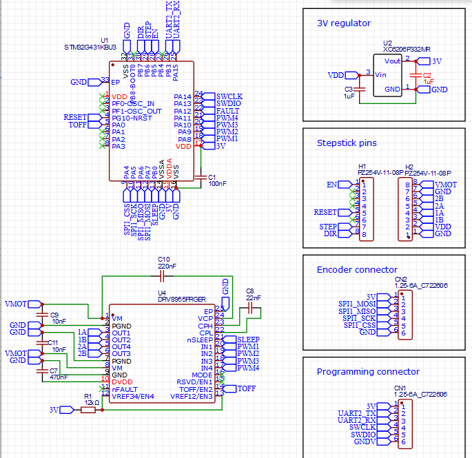
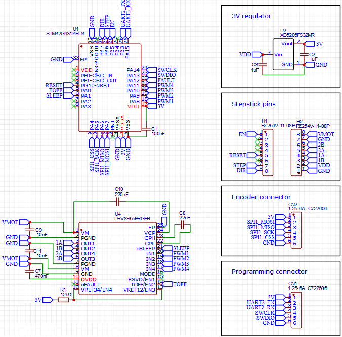
I had originally planned on making it BLDC-only with DRV8313, but these 4 half-bridge chips should make it usable for both. I’m torn between using STM32G031 for its low cost and small size, or G431 for its better performance and large flash space. I don’t think we really need the performance, but the flash would allow use of the full Commander interface rather than a custom stripped down version like I usually do. And it could be sold with a pre-installed firmware including the BLDCMotor, StepperMotor, and all the sensor classes so it can be configured for all sorts of setups with only an FTDI adapter.

Reply to another post from the other thread:

No, it also needs an onboard MCU to read the encoder and run SimpleFOC. The motherboard just sends step/dir signals, it doesn’t receive any feedback.

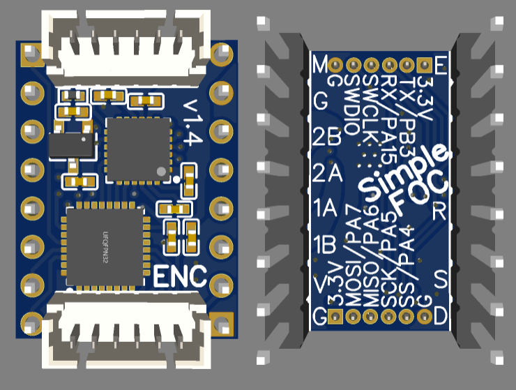
I haven’t seen any closed loop projects that are a drop-in replacement for the stepstick footprint. I agree it is getting a bit outdated, but the only competing format I’ve seen is BigTreeTech’s EZ driver, which is like a classic PC expansion card slot. That does allow for larger driver boards, but it hasn’t been around long enough to see if it will catch on.

Semi related, myself and @Copper280z had pretty great experience with the 3-phase stepper code (now in drivers lib) that lets you use normal BLDC drivers on stepper motors (with one end of each phase joined together as the third phase). The only real limitation there is that your phase to phase voltage is lower than with a “real” 4 half-bridge driver, so you only get about 70% of the power supply voltage without overmodulation. But even with that, I found it sufficient for a lot of tasks!

There are boards from Mellow which still use these driver ports and they are RepRapFirmware compatible. It would probably be good enough to put the step/dir interface there and have a separate driver board near the motor?
Or have a dumb connector board with the stepstick layout and the controller/driver can be NEMA-(11,14,17) size? That would allow using magnetic encoders, too.

For development it might be better to make a stepstick “adapter” first, so the initial test design can be a bit larger and easier to work with…

Yeah, that’s the most common approach I’ve seen for closed-loop on 3D printers. But that locks you into a particular motor form-factor, whereas I’d like it to be usable on as many different motors as possible so people can play with new designs.

If anyone else wants to try a slightly less cramped version, I’d suggest designing for the BigTreeTech EZ slot mentioned in my previous post. Then at least you can buy motherboards to use it directly, and they already sell adapters.

Here’s my first attempt at routing with STM32G431 and DRV8844. The reset and sleep pins were a lost cause, so it will be possible to brick the MCU if you flash a bad firmware and need hardware reset. At best I could make a tiny exposed copper area next to the chip where you could manually operate it.

It ended up being better to have JLC assemble the bottom layer, and manually solder just the MCU on the top. There’s also a capacitor for the DRV’s internal 3V regulator that I had to put on the top layer, but I don’t think it’s needed anyway since the regulator output is not used.

There’s one potentially fatal problem, that I had to squeeze the “enable” trace inbetween the DRV’s thermal pad and pins. There’s not quite enough space as-is, but it may be possible to reduce the size of the solder pad on the PCB and count on the solder mask to make sure no solder connects the trace to the pad on the chip.

Otherwise I think everything is good. Power traces are not as fat as I’d like, but not too wimpy. I also wish I could fit one than one via per line.


EDIT: Second attempt, using DRV8955. This one is much better. Ready for showtime, I think. Fatter power traces, all components on one side (although the driver will still have to be manually soldered since JLC doesn’t carry it), reset pin connected, and no sketchy practices like routing along the outer edges of the board. I even got the driver fault pin readable by the CPU, though it’s not really necessary. The enable pin goes to the CPU, and then CPU will be responsible for activating the sleep pin on the driver.

One thing that really helped is that I found a smaller voltage regulator on the JLC basic parts page, which also uses smaller filtering capacitors. Maximum input is 6V, but I think the VDD pin should always be 3.3V or 5V. The VDD-to-GND filter cap is father from the regulator than I’d like, but hopefully it will be ok.


4 Likes

Oh wow!
That seems very interesting, I have to try this out.
I’m wondering what happens to the pole pairs numbers. Also the phase resistance becomes nonsimetric right?

1 Like

Actually, I am not sure of the math for the phase resistance! I just used the resistance of one phase, but I never tried to see how far off the current was. The pole pairs stay as normal, I think. There was a paper we were using to implement it, I can find it later.

Let me know if it works for you! There was a lot of chatter about it a few months ago on the discord that spawned the #stepper-motors channel. You can see me using it with one of the nucleo IHM BLDC shields : https://youtu.be/Vx6fxW4_j_4

I love your curved pours!! looks really great!

1 Like

Those encoder traces run all across the PCB… wouldn’t it be easier to swap the encoder- and programming port?

Might be worth a try. Either way you have 4 lines crossing the high power area, but since the SWD pins are on the top side of the CPU, you’d only have the two UART lines headed upward from the bottom, rather than four SPI and two SWD, so the lower area might be less congested. Not that there’s much left to be gained by it. Maybe connecting the MSx pins to CPU pins 25-27 for more GPIO, but I’m not sure if that would be useful for anything.

My corncern was, that the encoder lines are busy while the powerlines are active, too.
That’s not the case while flashing new FW, right?

Oh, are you thinking of potential for noise on the encoder lines? That might be worth doing. I’ll give it a shot.

EDIT: Here we go. It was an interesting battle. The fault pin and its pullup resistor had to go, and it still feels cramped despite a large portion of the back side being unused. The UART pin vias at the top left of the CPU create a pinch point where the 3V and VDD lines have to squeeze through. But with the original UART pins at the bottom right of the CPU, there was an even worse pinch point below them.


EDIT2: I decided to go another round with it, and I think this one is ready for production if anyone wants to give it a shot. It will probably be a while before I do anything more on this project.

Notable changes:

  1. VDD capacitor is now over with the voltage regulator.
  2. TOFF pin is now accessible, which will allow selecting between 3 of the 4 possible off time settings.
  3. I realized it would be smart if both connectors have 3V and GND on the same pin so nothing will blow up if you accidentally plug your cable into the wrong one.
  4. Added more information in the silkscreen. Label for the encoder connector and version number on the top side, and SimpleFOC stamp on the back to clarify that it’s not a standard stepstick.


2 Likes

Is there any reason we couldn’t use a BLDC IC and just tie the two phases together creating a single tap?

Is there any reason we couldn’t use a BLDC IC and just tie the two phases together creating a single tap?

You can connect a 2 phase stepper motor to a 3 phase BLDC driver. I did this and it works it has some disadvantages.
If you have a single power supply, you have to switch the common connector between the two phases. You can make a cycle with 2 steps. In the first step you drive the first coil and in the second step you drive the second coil. The disadvantage is that you get only half the power compared to a stepper motor driver with 4 half bridges.

1 Like

That was the idea and also increasing the GND/cooling pad size for the driver.
For the latter reason I like your design before edit2 the most. It has a nice big slab of copper around the vias.

I did this, there is some code in the SimpleFOC drivers repo, see HybridStepperMotor implementation. Similar to @ChrisMicro approach but your Vmot is limited to 70% of the power supply, so more than half but not quite as much as if you had a dedicated driver.

3 Likes

How about this? Still not as wide open as that other one, but I don’t want to give up the TOFF pin, so I don’t think there’s any way around having a split down the middle. But I did manage to get some ground area under the step trace now, which is one of the most important not to have noise on.

Changes:

  1. Found a spot for a via below the CPU and moved the sleep pin there so it can follow alongside the TOFF line
  2. Spread out the capacitors a bit so the 3V line can pass between them on the top layer on its way to the encoder connector so it doesn’t cut through the ground area on the back.
  3. Scooted things around up at the top so I could add some more ground vias to get it all connected up better.
  4. Smoothed and fattened the curvy motor traces a bit, which I meant to do before but forgot.

Now I really need to leave this thing alone and get some more important work done :slight_smile:


1 Like

LCSC finally got 5 of the DRV8955 in stock, so I went ahead and ordered a batch of these. $3 for PCBs, $40 for components, and various fees and tax and shipping added up to $68 total, minus a $9 coupon, so about $12 each. Larger quantities should make it under $10 if I solder the connectors myself (only reason I didn’t this time is because I don’t have the right kind on hand, and it would have been more expensive to order them separately).

One thing I’m not totally sure about is leaving the nFAULT pin floating. According to the datasheet it needs a pullup resistor, and certainly that’s true if you’re going to read the pin, but due to space constraints I was just going to ignore it. If it is a problem, I can solder bridge it to the neighboring VREF pin, which goes to a pullup. nFAULT’s normal open condition shouldn’t interfere with it. And if a fault does occur, the driver will be shut down so it won’t matter that it’s incidentally driving the VREF pin low (which sets the current limit to 0).

2 Likes

You can global order for free (free as you only pay the supplier and JLC doesn’t charge you for the service). Then JLC keeps it in stock for you. I’ve done it multiple times in the past during the parts shortage or if I need a rare/unique part.

Cheers,
Valentine

2 Likes

Not the same chip, but I had a buck converter I was using which had a floating nFAULT pin which was supposed to be pulled up, but totally did not work when left floating, even though it is jut an indicator and not meant for disabling the buck. I’d make sure to fix it on your boards!

1 Like