I have a few 3D printer boards from Fly/Mellow which are designed for TMC-stepstick drivers.
The guys who developed the RepRapfirmware-branch for it might be interested in your design. (namely jay_s-UK and gloomyandy )
TMC drivers can be configured via SPI or UART. Do you implement a similar config path?
Wow, I had no idea they provided such a service. Here’s a page I found about it: How to use JLCPCB Global Sourcing Parts Service?
I’m surprised this particular driver isn’t well stocked already since it has such good specs, but for larger quantities it will be better to use global sourcing anyway since it’s the most expensive component on this board and LCSC’s price for it is about 50% higher than Digikey and Mouser.
The current design is only configurable via external cable. I’m having trouble finding information on which stepstick pin(s) I should use for UART. Maybe MS3? It looks like the Trinamic drivers have a single wire bidirectional UART, so I’m not sure how to emulate that from the STM32 which uses two wires. Maybe if I just connect the STM32’s RX to stepstick MS3, it will be able to receive UART commands at least.
I wish we would have had this discussion before I placed the order But at least the boards themselves only cost a few bucks. I can transplant the components from one of these to test the next revision.
Another afterthought is that it would be nice to have a pin for sensorless homing (activated if the motor is applying torque but fails to move for some amount of time). I’ve seen some motherboards with integrated TMC drivers that have the DIAG pin accessible for that, but no stepstick type drivers with a pin labelled DIAG. Maybe I should just have a single 2.54mm pin sticking up from the board somewhere that you can connect a jumper wire to the motherboard endstop pin.
For global sourcing, you need to pay not only the price of the part, but also some sourcing fee, I don’t think it’s negligible. The last time I looked at this, the LCSC part ended up being cheaper, even though you can buy the bare part for much less. The best thing you could do is find a chinese vendor inside the mainland which has the part, then mail it from that shop to JLC and they will put in your inventory via consignment.
The wiki pages from fysetc are a good source of information. Sometimes you have to read between the lines and some info got lost during translation. Here is the link to a UART config example.
Most boards using the stepstick pattern have a bunch of extra config jumpers.
DIAG is always on an extra pin. Not sure if it’s always on the same location on different driver boards, but on two drivers it’s there
The MKS drivers do have the actual PDN_UART pin on stepstick RST, but have it connected via resistor to MS3. Maybe for compatibility with both kinds of motherboard? It does look like FYSTEC uses stepstick RST for UART, connected via JP1 in the schematic diagram here FYSETC F6 - FYSETC WIKI
Not good for me because I’d like to keep the STM32 reset pin accessible. But upon further consideration, I don’t think the UART connection would be such a good idea anyway since it would need support in the 3D printer firmware. All the settings needed to configure a BLDC motor would be a lot of work and maintenance burden for a niche product. Better to stick with my original plan to use SimpleFOC Studio via an FTDI adapter.
I do wish I could use that DIAG pin placement, but it looks pretty hopeless. I can fit an upward-pointing 2.54mm pin in the lower right area, though. Not aligned to the grid defined by the other pins, but it should work for a jumper wire to the endstop pin. It greatly reduces the conductor cross section from the lower ground pin to the driver, but the upper ground is probably all that’s really needed, since there’s only one VM pin.
I’m using a BLDC motor with sFOCs stepDir interface on a 3D printer without any Comms except stp and dir. It doesn’t bother much, since we don’t need standby- or idle current reduction. (unless you want to drive a stepper motor with it?)
Would you have to remove the driver from the controller to flash it? I know that the Duet3D controller has a protection circuit which allows to feed/flash the board via USB and also have a 24V PSU running.
But I also remember reports of melting USB cables from bad ground loops…
It should be ok, since the 3.3v rail is isolated by the regulator so flashing it while the printer is off won’t feed power back into the motherboard circuitry. And if the printer is on, you can leave the ST-Link power wire disconnected, or use v3minie which doesn’t supply power at all. UART communication only needs 3 wires, TX, RX, GND, so that should be ok too. If you do connect the ST-Link or FTDI’s 3.3v supply to it while the printer is on, you could potentially get a small current if that 3.3v is not exactly the same as the 3.3v from the onboard regulator.
I like being able to disable the motors and move the printer around by hand (changing filament with a spiral extruder, and quickly moving the printhead near the home position before starting the next print), so I definitely want the enable pin connected. But otherwise this is mostly about ease and cleanliness of construction, having the drivers plugged into the motherboard rather than having to mount them separately. I suppose it wouldn’t be too bad with my stackable Lepton design since you’d only need one mounting point, but this is better still.
It can drive BLDC or steppers since it has 4 independently controlled half bridges.
EDIT: Brilliant idea for the next version: Use DAC to control the current limit VREF pin. That will give nFAULT exclusive ownership of the pullup resistor, and may eliminate the need for voltage-based current control and its associated kv and resistance parameter tuning.
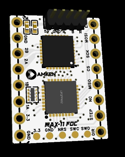
The boards have arrived! Soldered the header pins on one of them, but haven’t fired it up yet. I hope that fault pin isn’t a problem, because I had JLC solder the connectors so I wouldn’t have to order them separately, but they block easy access to the two pins that may need to be bridged (bottom two on the left side of the driver chip in the photo)
This 32-pin MCU barely fits, so you’d have to do double-sided SMD. But that means you’d have room for the larger DRV8844 as well, which is $2 versus $5 for the DRV8955. Or DRV8316 if you don’t care about supporting stepper motors. And if you don’t care about compatibility with 3D printer motherboards, you could make a tiny single-sided driver with RP2350 and DRV8844 for about $3.50 in components. You’d save some board space that’s wasted by unused header pins, but lose some because you’d have to include a bulk capacitor and more low-voltage management. Stepstick cheats by having a capacitor on the motherboard underneath, and separate high voltage and 5V supply pins.
Ooh, very nice. And only $3 apiece from Mouser (LCSC doesn’t have them yet). With a 4-layer board and only 3 phases supported, I may be able to fit all the resistors necessary. Although I’ll probably have to give up my newly added home pin…
I still need to test out the v1.4 boards that I ordered. I’ve been spending all my time working on Gooser, but I think it’s ready to order now.
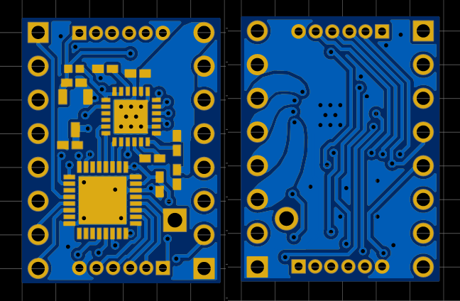
Here are the stepstick v1.5 images (home pin added, and fault joined to the VREF pullup and connected to a GPIO so it can be read). I also added inner layers so it can optionally be produced as a 4-layer board, because I was going to include it in a panel with other 4-layer designs and cut them apart and assemble myself to save money (JLC is about the same price for anything up to 100x100mm). But it turns out ordering the $7 solder stencil adds $20 to the shipping cost, which defeats the purpose.
Hello everyone. Just recently discovered SimpleFOC. I tried it on a couple of microcontrollers and was super impressed. So, I set out to design a Step Stick based controller that I could use in any 3d printer board which supports SPI. Turned out I wasn’t the first to have that idea when I discovered this post. Impressed and inspired by @dekutree64 's work, I put my own spin on it and designed a new board. I am using MAX22211 by Analog. This is a new chip and is very promising. It is a simple to use 36V, 3.8A Two H-Bridge chip. I originally designed it with RP2350, but wasn’t too impressed with the ADC performance when I tried it out. So I designed this with the trusty STM32G431.
My goal is to use these for a project that I am working on where I am using Nema17’s with 1000PPR optical encoders built in.
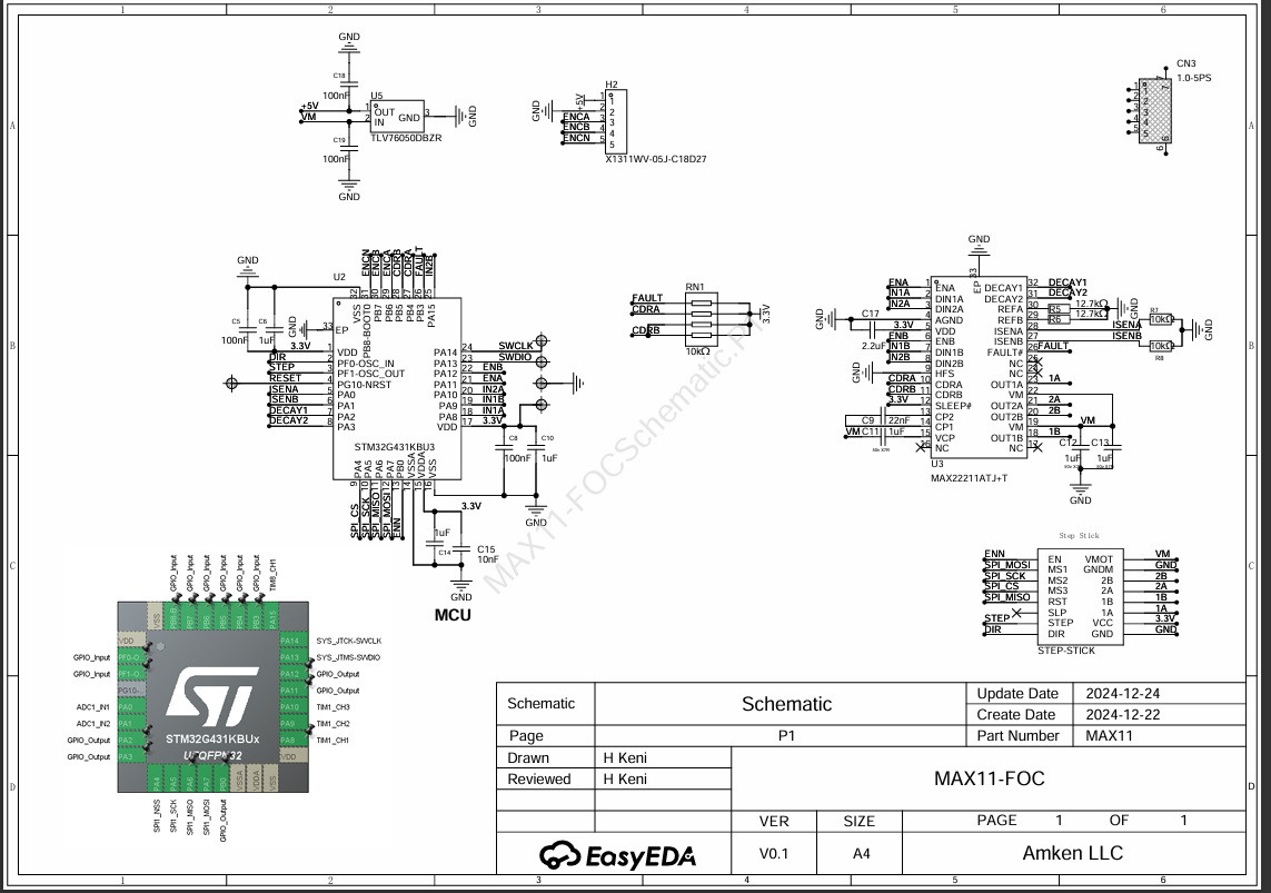
I am posting the schematics here. But, in full transparency, I don’t plan on making the gerber files open source. However, if any community member would like to try and test these, I am willing to send a couple of ones for free and if you need more, I am willing to send them at cost. I just sent these off for PCB production. I should have them ready in a couple of weeks time.
SWD for programming. But if I ever commercialize the product, then I will probably remove the SWD pads and write a bootloader which uses SPI
Primary intended comms is using SPI (Sort of like TMC5160 or similar), but will also have STEP/DIR for compatibility with existing controller software such as Klipper/Reprap
ABN encoder with onboard 5V supply
3.3V will come from the main board
Current limit set at 2A per H bridge side. This I feel is sufficient for a NEMA17 with some margin
Yeah, I regret wasting money getting the DRV8955 version fabricated since I learned about MAX2221x shortly after and it’s a better chip with real current sense.
Does MAX22211 only work with steppers? It looks like it from the datasheet. I’m primarily concerned with enabling use of 3-phase BLDC motors on 3D printers for spiral extruders and linear motors, so I’d rather use MAX22213 which has 4 independently controllable H-bridges. I made a brief attempt at designing a board for it a few months ago, but was unsuccessful and haven’t gotten back to it yet.
Yours has components on both sides of the board, correct? I may have to do the same. Do motherboards typically supply 3.3V to the drivers these days? The 3.3V regulator would actually be a problem in that case since it needs a bit higher voltage to function properly, and removing it may free up enough space for single-side assembly. In your case adding the 5V regulator moots that savings, but I think I’ll leave it out since I’d planned on using magnetic encoders which mostly run on 3.3V.
I do like the idea of having SPI communication with the motherboard via the stepstick pins so you can potentially configure the motor parameters from the printer without a computer connection (although it would require adding a new menu in the printer firmware). Is yours a standard pin configuration, or does it rely on motherboards having jumpers to connect them up in any way you like? It’s hard figuring out what is the best pinout to use when there’s so much variety on the market.
I have a few BTT boards (Manta8, SKR3, Octopus max ez). All the boards that support TMC drivers supply 3.3v. I agree with you on the confusing number of different implementations. However the pins for SPI, I selected are based on the BTT boards I have, which I believe are standard among most Chinese brands such as BTT, Makerbase and Fystec. At least in the Ramps1.4 based boards. My end product is a Pick and Place assembly machine. I am in the process of designing a 10 driver board where I want to use these stepstick drivers. I also wanted the option of being able to use off the shelf boards and hence the interest in this design. I am also designing the firmware for my machine so I am not using 3d printer firmware.
As for Klipper firmware changes, i do not think that the C (microcontroller) code needs to change. I’d have to write the Klippy (python) support for these drivers to be able to communicate over SPI. Similar to how you would setup a TMC driver in Klipper. Klipper would be oblivious to the fact that there is a STM32 running on the driver. The driver would have to implement what it wants to communicate with Klipper. The most basic setup would be like a A4988, where there is no comms, just listen to the step/dir signals and move the motor. The other end is have feature rich options where you can command the driver to operate in full SPI (without Step/Dir) mode where the SPi signals give the position/velocity etc. and not Step/Dir is used . Klipper does not implement what I call full SPI. Instead the SPI is used to configure the driver and to get telemetry. I will get around to writing Klipper support once I’ve had a chance to test these babies out.
What are some lessons learned from your experience. Btw, I’d like to wish you a very @dekutree64 happy holidays and thank you for responding to my post.
Nice design, and I look forward to reading some more about your PnP machine…
This is the really tricky part, and would require fairly fundamental changes within Klipper, which is currently quite married to its idea of step-dir control.
There’s been some attempts on the forum here and on discord to link Klipper to SimpleFOC, but so far they’ve used the StepDir interface…
Yep. I read through most of those. That is the only reason I chose to include Step/Dir in my design so as to maintain Klipper compatibility. I honestly think that the way Klipper is married to using Step Dir is outdated.
Take for example the way it uses the TMC drivers, most of the good stuff in a TMC is only possible when you use SPI interface for position/velocity control. The TMC5160, 5420,2240 all have in built 6 or 8 curve generators. All that is useless with Klippers trapezoidal ramp profile and Step Dir interface. I don’t expect Klipper to change. They don’t have any incentive to do so.
When I said “the other end”, I meant the other end of the spectrum, A4988 being the simplest and SPI being full featured. Klipper, Reprap, etc. is sort of in the middle. I haven’t seen a multi axis controller that is also full featured. Maybe LinuxCNC can be used to create a “full featured” controller, maybe….