Low side current sensing for stepper motors

Hello guys,

I’ve recently noticed that the SimpleFOC’s low side current sensing support for stepper motors is currently incomplete and do not really work as expected. I decided to try looking into this issue and hopefully solve it eventually. The discussion is mostly happening in Discord, starting here

At @Antun_Skuric’s request, I will be posting here a condensed version of the discussion happening in Discord, just to keep this discussion as public as possible

Context

First, I’d like to explain two main ways to connect current sensors when using the low side current sensing approach for stepper motors:


Let’s take a closer look at the first one, which has two current sensors. Let’s analyze all the ways that current can flow when the motor is running. For simplicity, we only consider coil A. All the currents didn’t fit on one diagram, so I divided it into two, left and right:

As can be seen, there are four possible current paths:

  1. Red. {Q1: ON, Q2: OFF, Q3: OFF, Q4: ON}. Flows top to bottom when the motor works as a motor. Flows bottom to top when the motor works as a generator
  2. Blue. {Q1: OFF, Q2: ON, Q3: ON, Q4: OFF}. Flows top to bottom when the motor works as a motor. Flows bottom to top when the motor works as a generator
  3. Orange. {Q1: OFF, Q2: OFF, Q3: ON, Q4: ON}. Can flow in both direction. This is a low side “freewheeling” current
  4. Purple. {Q1: ON, Q2: ON, Q3: OFF, Q4: OFF}. Can flow in both direction. This is a high side “freewheeling” current. It is shown in dashed lines because this current path is not currently used by SimpleFOC

Then, let’s analyze the topology that has 4 current sensors in the same way:

All the colors are explained above

Some facts about these topologies:

  1. When using two current sensors, there is no way to measure any “freewheeling” current because it simply does not flow through the current sensors
  2. When using four current sensors, the low side “freewheeling” current (orange path) could be measured. The high side one (purple path) is still invisible for the current sensors
  3. Currently, SimpleFOC only “supports” the two current sensors approach, simply because the LowsideCurrentSense class only supports up to 3 ADC pins. The word supports is in quotes because this support doesn’t really work the way it should, as will be explained next
  4. The current sensors must be bidirectional, otherwise they will not see some of the currents

To be continued…

2 Likes

Let’s figure out what’s wrong with the current SimpleFOC low side current sensing implementation for the stepper motors. There are two issues:

  1. The sign of the measured currents is not always correct
  2. Current sensors ADC sampling and PWM not synchronized correctly

Let’s look into these issues one by one

The sign of the measured currents is not always correct

Let’s look at an example. Let’s say, at some point of time, the current flows along the red path, top to bottom:

  1. The current flows through the motor coil top to bottom, let’s consider this direction to be positive for the motor coil, i.e.:
I_a^{coil} > 0
  1. The current flows through the current sensor top to bottom, let’s consider this direction to be positive for the current sensor, i.e.:
I_a^{sensor} > 0

Let’s say that after that the current starts flowing along the blue path, but the direction of current through the coil A is the same, i.e.:

I_a^{coil} > 0

It can be seen that the direction of current through the current sensor has changed because the active pair of transistors has changed ([Q1, Q4] → [Q2, Q3]):

I_a^{sensor} < 0

So it can be said that depending on which pair of transistors is active, either [Q1, Q4] or [Q2, Q3]:

  1. The current flowing through the motor coil is the same as the current measured by the current sensor
  2. The current flowing through the motor coil coincides in absolute value with the current measured by the current sensor, but their signs are opposite

Fortunately, there is a simple formula that relates the current flowing through the motor coil and the current seen by the current sensor:

I_a^{coil} = sign(V_a) * I_a^{sensor}

The problem is that this formula is not currently accounted for in SimpleFOC, instead this one is used:

I_a^{coil} = I_a^{sensor}

The PR fixing this issue is here

To be continued…

EDIT - reconsiders my previous post here.

this is my low side current sense, it works well

I have tried to look for some information on internet about the topologies for current sensing used with H-bridges. I did not succeed in finding any good collected information. I have been using brushed DC-motors with four quadrant control using H-bridge, and have discovered some of the issues. And I think some of the issues do also apply for low-side current sensing when you use stepper motors and three phases as with BLDC motors. So I am sorry - this have to be a long comment. In general this has a lot to do with how you make the MPU hardware timers trigger the ADC(s) to measure the current at right point in time.

I think this link was the best I could find on the issue, and I recommend to read it:
https://www.allegromicro.com/-/media/files/application-notes/an296276-current-sensing-in-motor-drives.pdf?sc_lang=en

I did also find one application note from Texas Instruments here. But I am surprised, that they do not describe the topology with one shunt in every lower leg in the H-bridge:
https://www.eeweb.com/wp-content/uploads/articles-app-notes-files-current-sensing-in-an-h-bridge.pdf

I have also seen comments in this forum describing the use of ADCs with DMA, so they sample many values and they may not be synchronized with the PWM timing. In general you will have noise on the current signals generated when the half-bridges switch voltage, and with DMA this way, you will also have the problem, that you may need to reject some of the measured values due these switching transients.

For stepper motors I think SimpleFOC apply sine and cosine currents in the two windings, and in this way you apply micro steps in the positioning of the motor angle.

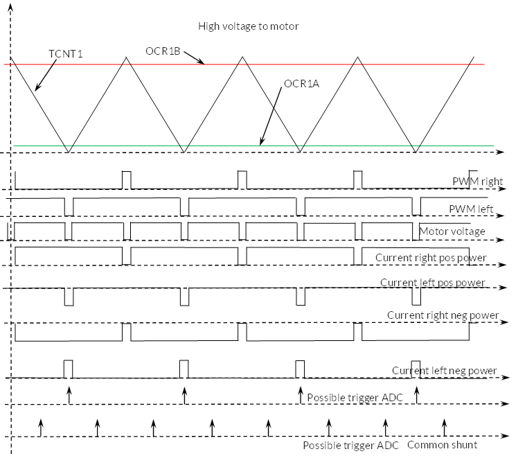
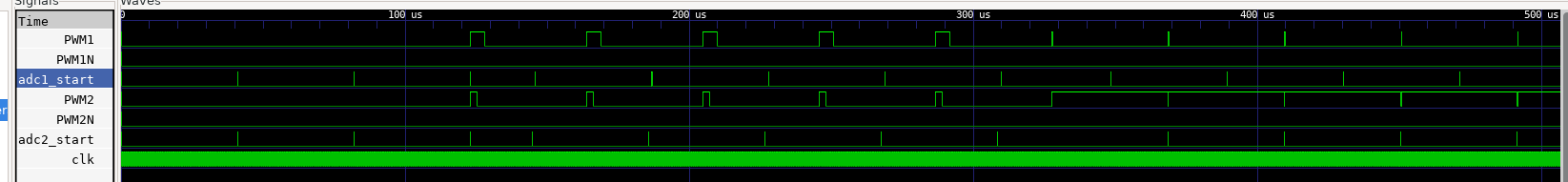
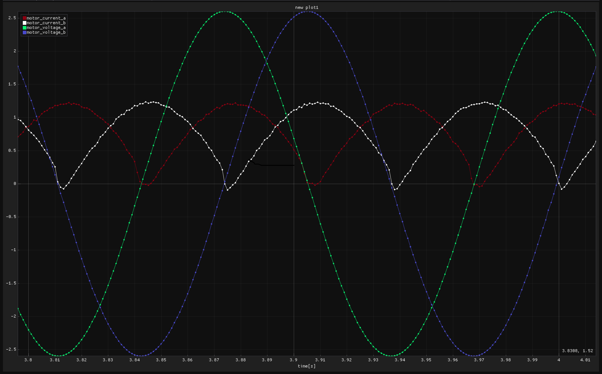
In the following I describe one way to control an H-bridge and do the triggering of the ADCs. Look this set of curves:

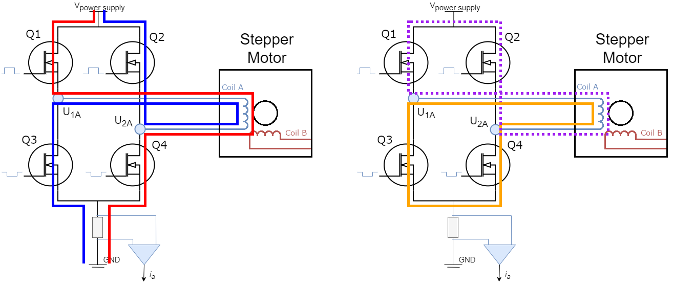
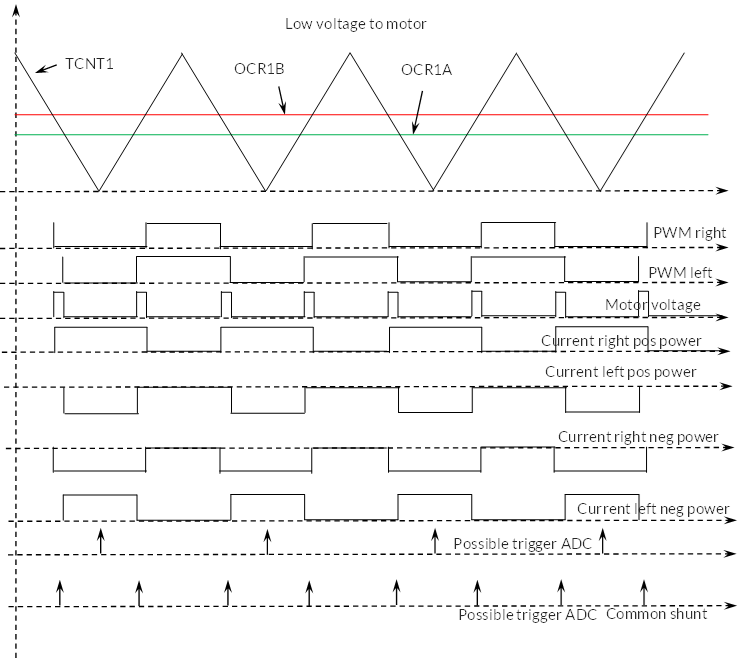
In the top you see a hardware counter, TCNT1 in the MPU counting up and down. This value is compared to two other registers OCR1B and OCR1A. You set the values so (OCR1A + OCR1B)/2 = mean value of TCNT1. A digital signal is generated from TCNT1 >= OCR1B, and it controls the right side of the H-bridge. And similar for the left side. The motor will see a PWM frequency of double the Timers PWM frequency. This case is with a low mean voltage supplied to the winding.

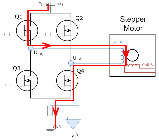
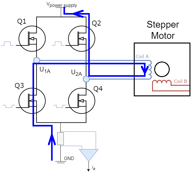
Further down you see currents in the two lower legs of the H-bridge (and it includes the free wheeling diodes). It is assumed the self inductances of the windings are high, so the current do not change much (it is normally not that ideal). You do have two situations, with positive and negative power to the motor, and they are both shown.

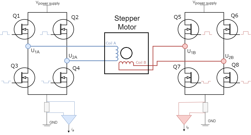
The most important part is how you trigger the ADC or ADCs sample hold circuit to read the current value and two ways are shown. I think the first one marked “possible trigger ADC” is the normal way. Most MPUs got hardware, so you can trigger the ADC by the timer being at lowest value. However, if you use a common low side shunt, you will not measure the motor current. But it will be OK to measure the current in one leg as @zhangzq71 describe.

If you use a common shunt you need to trigger the the ADC like shown at lowest curve. The ADC is triggered when TCNT1 pass its mean value (and perhaps only half the times). It is not all MPU, that got an easy possibility to do that, but I guess newer MPU are able to do it, but it is more complicated. If the motor voltage becomes close to zero, the time window you are able to measure the current becomes narrow, and the current measured will be like undefined. I don’t like that at all, and to me it disqualify this topology for full four quadrant control of a DC motor. You need to have reliable current measurements near zero voltage to the motor.

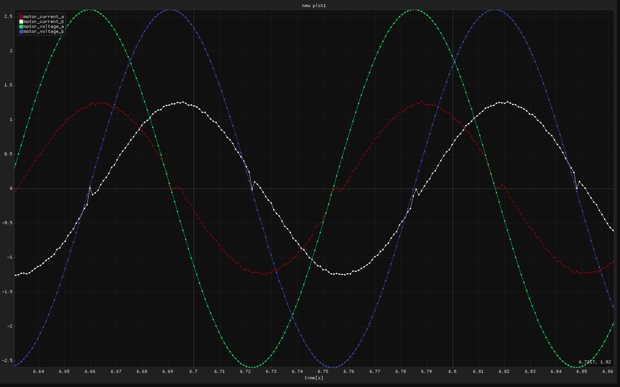
But this is not the whole story, because you need to consider high voltage as well as you see here:

When the voltage becomes near max, you will have a very short window to measure the current when you trigger the ADC in the traditional way, and then this measured current will become unreliable. One way to solve this problem is to limit the max voltage to the motor like to +/- 90% of full voltage. Then you will likely always have sufficient time to measure the current and the method from @zhangzq71 still apply.

If you want to utilize the full voltage to the motor, you need to do two things:

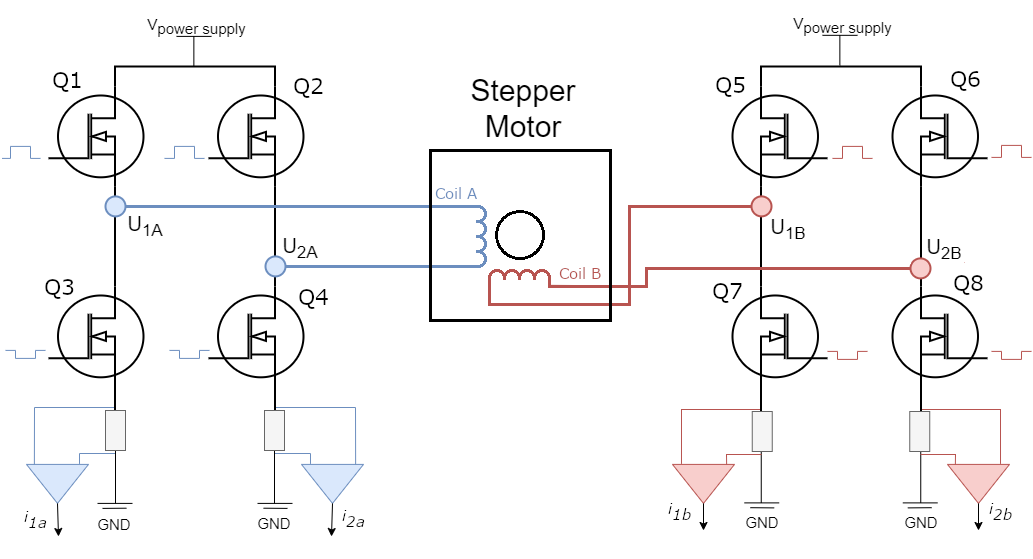
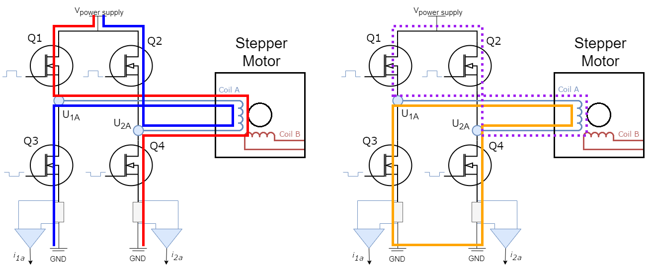
  1. You need to have a current shunt in both lower legs of the H-bridge.
  2. You need to shift the timing of the trigger to the ADC at high voltage values to the second position shown. If you measure the currents individually in each leg, you need to know where to measure.

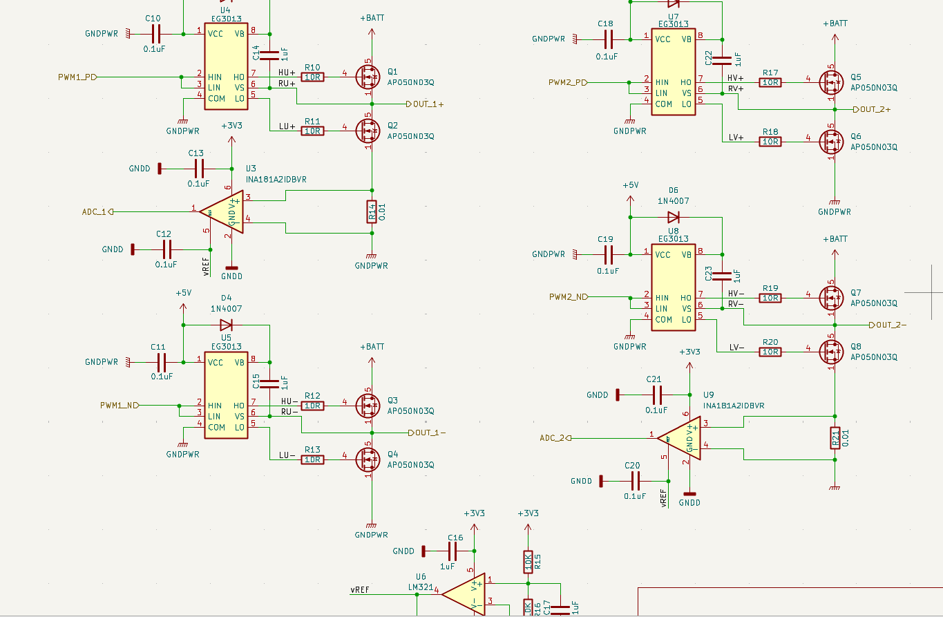
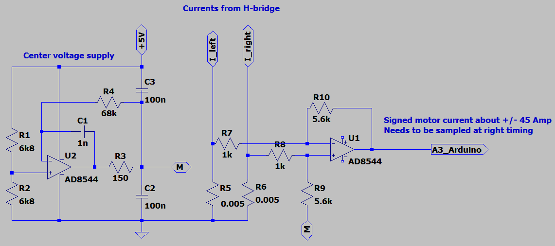
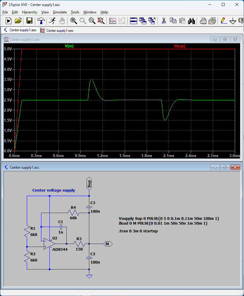
When you use a shunt in both legs, it is possible to use a sense amplifier as you see here and then only use this signal with one ADC:

With the normal timing of the ADC trigger you will then measure the sum of both currents in the shunts this way. However, with the alternative ADC trigger timing at high voltage you will only measure one current, and will need to multiply the measured signal with a factor two.

I hope all this will make sense to you :slightly_smiling_face:

The low side sense must need an appropriate time to measure. this picture shows the result when measuring the IA, IB in right time


and this shows the result not in the right time

My project uses a MCU+FPGA chip, PWM generation and ADC time was controlled in FPGA

Thanks @vmnnk for the post and the effort put into it!

@zhangzq71 that makes perfect sense.
This topology then removes the issue @vmnnk is solving here. As the phase currents have to pass through the shunt resistor. We were discussing in the discord forum if we need 4 shunts or not, but I guess that your topology proves that two are perfectly enough.

What are the timing considerations for this topology. Is the ADC conversion at the center of the activation time of the low-side mosfets enough, or is there something more to it.
What is your PWM modulation strategy?
In our case we are always keeping one side of the H-bridge connected to the ground and modulating the other one. I suppose you are not doing that?

1 Like

I think I made the argument, that the topology with two shunts only for the two H-bridges like proposed by @zhangzp71 cause, that you cannot use up to max output voltage. But I agree, that in many cases it will be sufficient to utilize up to about +/- 90% of the voltage, and then it is the best way to do it. I cannot recommend the topology with one common shunt for both legs in the H-bridge.

1 Like

For low side sense the right time to measure is important, here you can see, PWM1,PWM1N,PWM2,PWM2N are the pwm signal for the mosfet driver, adc1_start, adc2_start are the signal to trigger the ADC, as you can see the adc_start must at the center of the low state in a duty cycle.

and here is the video for my stepper controller, the RPM can be up to 4000RPM

1 Like

When I look at your diagram above, I see these PWM signals. However I like to know how you connect the two windings of the stepper motor to the outputs. I guess one winding is to from Out_1+ to Out_1-, and the other is from Out_2+ to Out_2-. Am I right?

4000RPM is very high for a stepper motor. Are you sure? When I look the video it seem to me that the max speed seen is about 600RPM.

1 Like

yes, Out_1+ to Out_1- is one winding, Out_2+ to Out_2- is another. The max speed in the video is 1200RPM. And it can not be stopped by finger at lower than 1500RPM, higher than 2000RPM it can be stopped by finger. The max speed is about 4000RPM, as you can see the max speed is 22329rad/s elec angle.

1 Like

I have looked at your recording on the signals. Now, I try to explain, what I see, and please tell me, if I am wrong. The initialization don’t matter to me.

First I see a low positive voltage to winding 1, and then I see an even lower positive voltage to winding 1. The trigger of ADC1 looks fine and it is far away in time from switching of this H-bridge. With positive power to the winding you will see a negative reading of the ADC_1 signal.

For winding 2 first part, I see a low positive voltage to the winding. The trigger timing looks fine and with positive power, you should see a positive voltage on ADC_2.

For winding 2 second part, I see a very high positive voltage to the winding 2. Then shunt measure the current in the negative leg, that is on all the time. The measured current should be reasonable, but you may get some transient noise in current signal due to the motor stray capacitance, when the other side in H-bridge is switching at the same time.

I like you to consider a very high negative voltage on winding 2. Do you agree, that you have got a problem with the current signal here?

The way you control the H-bridges are different from the scheme in my example above. You keep one side of the H-bridge low all the time while the other side is switching. I think this way is not as good as in my example, and I shall try to explain why. You like the low voltages made to the motor to be reasonable linear near zero voltage to the motor. When you make short timed pulses with one half bridge, the voltage may not reach the other side. This cause some non-linear behavior. This behavior is not desirable for the precise control of DC motors, but it may not cause so much trouble for step motors. With my scheme I get the short pulses by the half H-bridge at high voltage. But there this non-linear behavior do not matter that much.

I got one more comment about the Vref supply. It is not good practice to put a capacitor to ground directly on the output of an OP-amp, because it can create instability. Look at the way I make the center supply in diagram above.

1 Like

Blockquote
I like you to consider a very high negative voltage on winding 2. Do you agree, that you have got a problem with the current signal here?

That wave signal is just a RTL simulation not the actualy duty cycle to drive the MOSFET. And I forgot to mention that the ADC_start singnal will be trigger in the every beginning of the PWM cycle when duty cycle is 0. The ADC_start single will be at the middle of the low part of a PWM cycle. This is the test case

Blockquote
I like you to consider a very high negative voltage on winding 2. Do you agree, that you have got a problem with the current signal here?

I tried to measure the ADC signal when driving the MOSFET with about 2A IA,IB current, it still behavior the same way as in very low current.

Blockquote
The way you control the H-bridges are different from the scheme in my example above. You keep one side of the H-bridge low all the time while the other side is switching

I think it is ok in this solution, and I found SFOC using this way too.

Blockquote
I got one more comment about the Vref supply. It is not good practice to put a capacitor to ground directly on the output of an OP-amp

did you ever try this? In theory this must cause oscilation.

I am not that good in coding and RTL simulation, so I cannot comment on your test case.

Yes. I think this will be all right with stepper motors. The other way is better for DC-motors, and you and other readers know this method too by my comment.

Yes, I have actually used it more times with these general purpose Op-amps: TL084, LM321 and MCP6004. According to my theory, it should have a damped response with most Op-amps. I just now tried LTSpice on it, and this is a screen dump of the transient response for a 10 mA step load.

For a specific Op-amp you can optimize the component values to provide a better response, if you like to have that.

1 Like

Thank for your advise, I will try it on my side.

1 Like

Hi @Backflip and @zhangzq71,

Thank you for participating in the discussion! Here are my thoughts:

  1. The topology proposed by @zhangzq71 looks very interesting. It is definitely different from the two I mentioned at the beginning of this thread. I will try to understand this third topology in more detail a little later
  2. The topic regarding synchronization between PWM and ADC, which you both mentioned, is indeed very important. As I said before, current sensors ADC sampling and PWM are not synchronized correctly in the latest SimpleFOC code (in case of low side current sensing for stepper motors). Fortunately, there is a simple hacky way to fix this. Though I’m not sure how difficult it would be to fix this properly, without hacks. I’ll post more information on that later

Now, I would like to show some of my current results regarding the changes I have made to the SimpleFOC code. The first change I explained in this post. The second change concerns PWM and ADC, and I still need to post more info on that

Just to make it clear, I use the topology with 2 low side current sensors, this topology corresponds to the very first picture shown in this thread. I run the motor in the “MotionControlType::velocity_openloop” mode

This is how everything looks without my changes in case of standard latest SimpleFOC code. I used MCUViewer to capture the diagrams posted below. All colours are explained in the upper left corner of the image. In this case, motor_current_a and motor_current_b are the currents measured by the current sensors:

And here my changes to the SimpleFOC code are applied:

As you can see, there are some artefacts when the current crosses zero. I think they are caused by the stepper motor driver that I use, DRV8844. This may be a problem caused by the H bridge control signal time being too short, resulting in the DRV8844 filtering this signal out and not executing it. Similar artefacts can also be seen on an oscilloscope if, instead of the motor winding, a 1 ohm resistor is connected and the voltage is measured across it:

Also, these artifacts may be caused by the fact that in places where artifacts are present, the winding voltage is almost zero, which means a very small PWM pulse width, and the ADC may not have enough time to capture the current.

However, I did not notice that these artifacts had a significant impact on the FOC performance.

However, I did not notice that these artifacts had a significant impact on the FOC performance

This will not impact FOC performance if not using current loop.

And here my changes to the SimpleFOC code are applied:

I am not sure how did you capture “motor_voltage_a/b” in such so perfect sine wave while the “motor_current_a/b” are in such shape.

Hi @vmnnk and @zhangzq71

Thank you @vmnnk for providing some measurement results. I notice the low frequency of 8 Hz sine average voltage, and then the voltage and current will be almost in phase. It is evident, that you got some problem in measuring the current when the voltage pass zero.

It seem, that you already are proposing a change to the FOC driver code for stepper motors using two H-bridges. I like to sum up the considerations for controlling one H-bridge:

  1. You got two schemes in the control of an H-bridge:
    a) you keep one side of the H-bridge low and supply the other side with a PWM-signal for some time. And then you may shift side for some time again.
    b) Both sides of the H-bridge are active all the time. In this way the motor will see a PWM frequency of twice the controlling timers frequency. (I show principle above).

I prefer b) because the applied motor voltage will be linear to internal control signal at low voltages. I don’t see any reason to prefer a). Unfortunately, it seems, that the current SimpleFOC software use a).

  1. What kind of current sense topology are implemented:
    a) Common shunt for both H-bridge legs.
    b) A shunt in both legs.
    c) One shunt in one leg as proposed by @zhangzq71
    d) In line current sense.

I prefer b) for full performance and c) for a low cost solution. d) is likely to cause more signal noise, but it requires less critical software for trigger of the ADC(s). I don’t think a) should be used, because the current signal becomes undefined at low voltage.

  1. At what timing should you trigger the ADC(s) to measure the current(s)?
    This will depend of on the other choices. It is likely, that you need to change the timing depending of the actual applied voltage to the motor winding.

So for my best choice, the software should be able handle 1b2b and perhaps also 1b2c and 1b2d.

1 Like

@zhangzq71 Both of your comments are valid. And both are due to the fact that I did not explain myself well enough in my previous post. Let me try to improve on that:

This will not impact FOC performance if not using current loop.

You are correct that I did not use a current loop when recording the diagrams from the previous post. As I said, the motor was in “MotionControlType::velocity_openloop” mode. I actually was measuring the currents, but just to display them. In the “MotionControlType::velocity_openloop” mode the measured currents are not used for anything, you are right. I used the motor in this mode because in this case the currents are expected to be sinusoidal, so it is easy to understand from the diagrams whether the currents are being measured correctly or not. The more the measured currents resemble a sine wave, the better.

However, this part of my message refers to a different situation: “I did not notice that these artifacts had a significant impact on the FOC performance”. In this case, I am indeed referring to FOC performance, which corresponds to the following motor configuration:

motor.torque_controller = TorqueControlType::foc_current;
motor.controller = MotionControlType::angle;

I am not sure how did you capture “motor_voltage_a/b” in such so perfect sine wave while the “motor_current_a/b” are in such shape.

This one is simple:

  1. “motor_current_a/b” are the actual phase currents, measured by the current sensors
  2. “motor_voltage_a/b” are the coil voltage setpoints, generated by the SimpleFOC. These values are then used to generate PWM duty cycle

@Backflip Thank you for the great summary you posted! It makes a lot of sense to me, it would be great to have something like that in the SimpleFOC documentation…

I agree with the conclusions you have drawn. I think that in general it is reasonable to follow your reasoning, but if you are interested, in my particular case I am unlikely to be able to do so, and here is why:

  1. Regarding (1), “schemes in the control of an H-bridge”. You’re probably right, and option (b) is better than (a). However, you’re also absolutely correct that the option that SimpleFOC use currently is (a). I don’t think it’s easy to change, and I don’t want to get involved in it for now
  2. Regarding (2), “what kind of current sense topology are implemented”. Again, I probably agree with the conclusions you have made. However, in my case I actually try to use SimpleFOC for the existing hardware, CLN V2.0, so I have no choice regarding the topology

I should mention again that I managed to get option 1a2a working in the true FOC mode (with the true current control). I don’t see any major problems at this point. At the same time, I don’t plan to use my servo drives in extreme conditions, such as very high speed, very high acceleration, and so on

1 Like

I would hesitate to do that as well. I have looked at the documentation for the relevant timer in a STM32G4xx processor. The description of the timer takes up 142 pages, and you got a huge amount of settings to be right in order for you to make it do what you want. It is likely that someone already published some code that do it, but I would have a hard time to find it. And you like to see a fair amount of documentation on the code as well.

1 Like