I think the idea would be to use two complementary channel pairs, e.g. TIM1_CH1, TIM1_CH1N for one motor coil, and TIM1_CH2, TIM1_CH2N for the other coil. So instead of having one end of the coil negative and the other PWM between positive and negative, you’d always have one end positive and the other negative, and PWM which is which. I think having both ends negative at the same time would cause a braking effect and heating of the coil, so this should be more efficient.
For a first effort, you could probably make a StepperDriver class that uses the _configure6PWM and _writeDutyCycle6PWM functions so you don’t have to add any new hardware-specific code. It would set up an unnecessary third channel pair, but if the MCU pins aren’t needed for anything else then it won’t hurt anything to have them PWMing into the void.
But it will be a bit confusing, because it looks like the BLDCDriver::setPwm expects unsigned voltages, whereas StepperDriver::setPwm expects signed, so you’ll have to convert to unsigned for _writeDutyCycle6PWM. Something like this:
StepperDriverComplementary4PWM::setPwm(float Ualpha, float Ubeta) {
  float Umid = voltage_limit/2;
  Ualpha = Umid + _constrain(Ualpha, -voltage_limit, voltage_limit)/2;
  Ubeta = Umid + _constrain(Ubeta, -voltage_limit, voltage_limit)/2;
  _writeDutyCycle6PWM(Ualpha/voltage_power_supply, Ubeta/voltage_power_supply, 0, phase_state, params);
}
Or you could set Umid = voltage_power_supply/2. BLDCMotor has a variable modulation_centered to choose which is used, but since StepperDriver takes signed voltages it has to be done at the driver level here.
I think what @Backflip mean was not complementary channel pairs, because most of the gate driver has this function. I think what he mention is one side of a H-bridge does not keep the same state while other side driven by PWM.
It is entirely possible that I have no idea what I’m talking about. What I’m describing would be 8PWM if the MCU was directly controlling each mosfet. But in this case it only needs 4 timer channels because the half-bridge drivers each take one input, and output complementary signals to two mosfets. The two ends of each coil are complementary to eachother, and the two mosfets on each end of each coil are also complementary to eachother.
I did not consider “complementary channels”. I think it means, that you always set the state of each side of an H-bridge to opposite polarity. It might be a 1c option. I have not seen that option used with H-bridges, and I do disagree to the contrary, that it should be more energy efficient. If you control the H-bridge like that, you get a higher ripple current in motor winding for the same PWM-frequency used, and this will be less energy efficient.
You are right, that some applications make use of breaking of a motor by making a short circuit of the motor winding by keeping the two sides on the H-bridge (or three half bridges) at same potential. But in this case this state is kept for a much longer time, that the period you see with PWM timing.
This way of breaking can actually be a bit risky, because the currents can become very high and above what is safe for the power transistors used. For an application I use a quite old and slow H-bridge called BTS7960. It have got an internal safety feature, so it short circuits the motor when it see a two high supply voltage. In most cases it may save damage to the device due to over voltage. But in my case I have seen it cause a too high breaking current from a DC motor, that then damaged the BTS7960. So I think the best design is to make active breaking, while you control the current. If the power voltage becomes too high, you limit the breaking current.
It may actually be possible to use the software in some way like you drive a normal BLDC three-phase motor and only use the two phases. Then you set the voltage to the two phases like indicated post 4 from top in this thread. But you still have to figure out how to make the right timing to trigger the ADC(s), but it will likely be right except for the case of the voltage is near max.
@zhangzq71 I look forward to hear from you regarding the results from using the other scheme.
I have tried to use this scheme with the old Arduino AtMega328p MPU with one DC-motor. The timers here is much more simple. It will be more difficult to make this MPU control the two windings to the step-motor. It can be done, but it will seriously constrain the PWM-frequency to be used. I can supply you with some of this code, but I doubt, that it will be that helpful.
I looked back in my notes, and I am sorry to say, that I have to correct my statement. I still think the 1b is better option than 1a, but you may experience some “dead band” in the control in both cases. The reason is, that the transistors in a half bridge are switched with a time delay, to avoid both transistors are on at the same time. But it results in the case, that for a short time both transistors are off. At a fixed provided PWM signal for a low voltage to the winding, you will see a significant change in the voltage depending of the polarity of the current to the winding. This is due to this short time, that the transistors are off, but the free wheeling diodes will likely be on during that short time.
I have looked at this CLN17 design using the Texas Instruments driver, DRV 8844. Yes indeed, the only way of current sense is with a common resistor for both legs of the H-bridge or using in-line current sensing with another board. It do seem to work even though it is hard to trust the measured current near zero voltage.
Assume, that you encounter problems with a voltage less than +/-5%. I guess it might be possible to make a work-around in the control scheme like with these examples:
If you want to create a voltage of +4%, make one PWM cycle with a 13% voltage and the next PWM cycle with a -5% voltage. And then you repeat this.
If you want to create a voltage of -1%, you make one PWM cycle with a 5% PWM and the next PWM cycle with a -7% voltage. And then you repeat this.
Outside the +/-5% range you just make the normal scheme every time.
Depending of the PWM frequency, you might create some audio noise by that, and you will increase the power losses a bit, but I think it will be insignificant. I am not sure how much bad effect it will cause in a current control loop, but I guess you may be able to compensate for that.
DRV8436, DRV8428, and DRV8434 got only one common GND.
DRV8424, DRV8425, DRV8436, DRV8841, DRV8843, DRV8845, DRV8881, DRV8844(named solonoid driver) got a common GND for each H-bridge.
DRV8412 got four individual GNDs and one for each leg in the two H-bridges. It is likely due to higher current capability.
Therefore, Texas Instruments in general supports the idea to use one common ground and shunt for each H-bridge to measure current.
Texas Instruments also produce several drivers with one or more internal H-bridges to drive brushed DC motors, and perhaps some of them got more possibilities for stepper motors. I have seen that some of them got internal ways to measure current in the transistors. It could be an alternative to use one or two of them. https://www.ti.com/motor-drivers/brushed-dc-bdc-drivers/overview.html
Regarding ADC:
In general I think it is the same. Depending of the number of shunts, you are able to measure the current more often, whey you have one side to GND all the time with scheme 1a. When you use the scheme I show, 1b, you will normally only measure the current for every two PWM-cycles, that the motor see.
Regarding efficiency:
I don’t think it matters that much for stepper motors. For DC motors, you can have longer periods with one polarity of the motor voltage. With scheme 1a it will be only one of the half bridges, that carry all the switching losses. With scheme 1b these losses are shared. At low motor voltage with scheme 1a, you make very short pulses on one half bridge, and then one of the transistors will newer be turned on effectively before, it is switched off again. Then you will typically see like a half sine wave in voltage for this short pulse to the motor, and I think it will increase the switching losses compared to scheme 1b. But I cannot provide you with any evidence of that.
I just now try to do a calculation based on this. Please tell me if I may be wrong.
At 4000 rpm you should use a driving frequency, f = 4000 / 60 * 200 = 13.333 kHz.
EDIT: the right value is f = 4000 / 60 * 50 = 3.333 kHz.
The reactance of the winding inductance should then be:
X = 13333 * 2 * pi * 3.7 mH = 310 ohm
EDIT: the right value at corrected frequency is then 77 ohm.
In order to keep 1.5 Amp peak in winding, you need a peak sine voltage of 1.5 * 310 = 465 Vp. I am not sure about the supply voltage. But with a voltage of 24 V you will only achieve about 0.077 Amp (peak) in the windings and corresponding less holding torque.
EDIT: These values are wrong by a factor four again.
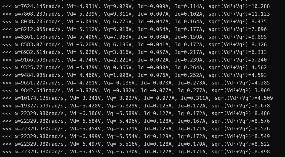
My current driving frequency is same as PWM cycle, are 25Khz. Actually there is little torque in 4000RPM, but it can’t hold the shaft by hand in 1500RPM, but it is easy to hold the shaft more than 2000RPM. Following is the testing result when I test speed.
Thank you for the test results. I like to know a bit more about how the values are obtained.
Did you use a PWM-based generator to supply the motor?
For each row in the table - are the values for voltage and current obtained at the same point in time? Did you choose some specific time in the electrical cycle to sample the values?
It seems that you see an impedance of motor winding like this:
w= 7624 rad/sek Z= 90 ohm XLcalc = 28 ohm
w= 9843 rad/sek Z= 14 ohm XLcalc = 36 ohm
w= 22330 rad/sek Z= 40 ohm XLcalc = 83 ohm
w= 22330 rad/sek should be a motor speed of 1066 rpm - right?
OK, so the voltage is not the direct voltage on the motor winding, but the calculated PWM mean voltage value based on the duty-cycle of the PWM used - right?
Thank you for clairyfying this to me, because I am not used to work with stepper motors. I had the frequencies and number of pole pairs wrong by a factor four in my previous calculations above. 1.8 degrees in data sheet means 1.8 degree per full step. And four full steps make an electrical cycle. So at 4000 rpm you should expect a reactance of the winding of 77 ohm.
OK, so the voltage is not the direct voltage on the motor winding, but the calculated PWM mean voltage value based on the duty-cycle of the PWM used - right?