Let’s figure out what’s wrong with the current SimpleFOC low side current sensing implementation for the stepper motors. There are two issues:
- The sign of the measured currents is not always correct
- Current sensors ADC sampling and PWM not synchronized correctly
Let’s look into these issues one by one
The sign of the measured currents is not always correct
Let’s look at an example. Let’s say, at some point of time, the current flows along the red path, top to bottom:
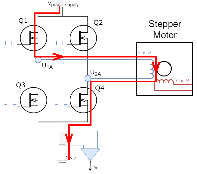
- The current flows through the motor coil top to bottom, let’s consider this direction to be positive for the motor coil, i.e.:
- The current flows through the current sensor top to bottom, let’s consider this direction to be positive for the current sensor, i.e.:
Let’s say that after that the current starts flowing along the blue path, but the direction of current through the coil A is the same, i.e.:
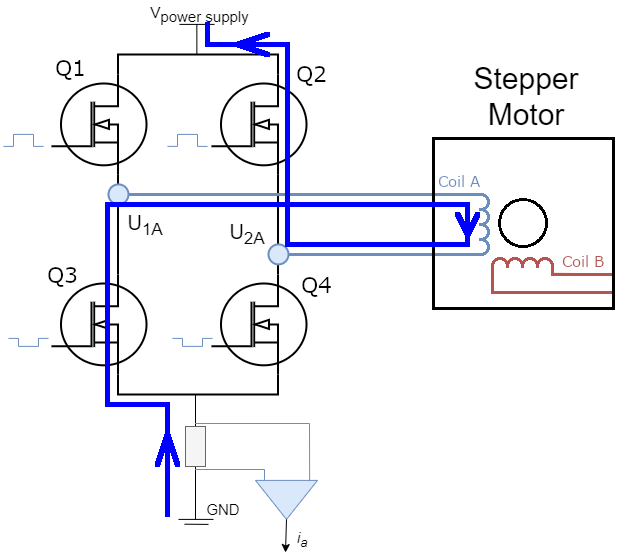
It can be seen that the direction of current through the current sensor has changed because the active pair of transistors has changed ([Q1, Q4] → [Q2, Q3]):
So it can be said that depending on which pair of transistors is active, either [Q1, Q4] or [Q2, Q3]:
- The current flowing through the motor coil is the same as the current measured by the current sensor
- The current flowing through the motor coil coincides in absolute value with the current measured by the current sensor, but their signs are opposite
Fortunately, there is a simple formula that relates the current flowing through the motor coil and the current seen by the current sensor:
The problem is that this formula is not currently accounted for in SimpleFOC, instead this one is used:
The PR fixing this issue is here
To be continued…