I don’t have the skills to design a board (yet) so does anyone have recommendations for a community board that can do roughly 30 amps at about 60v?
I don’t have a specific application aside in mind aside from make motor speen but I do want to build a board or two in an attempt to learn about motor control, circuit board shenanagins, and the limits of this project.
Not really. At 60V / 30A you need a board with about 30% headroom, which pushes your specs to 90V / 50A, and this corresponds to a 4500 watt board.
$300 for a 4kW is really cheap, usually an off-the-shelf board capable of that is probably close to $1000 or more of you buy it from China, or a lot more if you buys from US or Europe.
That’s why I’m referencing my boards, I know they work. I cannot vouch for others, I have not tested them, and they also may be better for your use cases, it’s up to you to check.
Check out my other works, too, you may find something that tickles your fancy.
Your boards were the first I found when I started looking. They called seemed pretty well done. None I could find fit both my purpose and budget unfortunately.
I will probably use the mosquito in the future if I really dive into this.
You probably have a little bit unrealistic expectations. Motor control boards are expensive to begin with, even DIY hobby ones. As you go higher on voltage/current, they get even more expensive.
You will have a hard time finding anything under $50, especially if you are in North America (including taxes and shipping).
And this is just the board. You will need a motor and sensor to go with this.
If you buy the driver board only, you need to add the MCU board cost too. Plus a programmer. Generally you need about $200 for the whole package, end to end.
You said 48 max so I assumed lower than 48v may be sufficient for your experimentations and education.
If you really need 48v max with 60v headroom then yes, the krakatoa is the only one.
I’m trying to help but I don’t see much to be done. Best would be to lower your voltage and current requirements and go for the lepton ($10 per board) or qvadrans ($14 per board).
If this is for education and experimentation you should be able to play around with the 12V/3A mosquito. You can run the mosquito with a 9V battery, the rectangular ones, on your desk, with no danger of electrocuting yourself or setting the house on fire.
Couple years back friends of mine started a large drone company. One night a battery shorted and burned about a $million of equipment and the entire work and research. They were lucky no one died. The company closed and they were on the street.
True story. The only thing left was one 100cm carbon fiber propeller, I hung that one on my wall to remind me of what a million dollars look like.
If the qvadrans are current limited because of the copper, could you not just add smd links, copper wires, or just blobs of solder on top of the offending tracks?
Does this screw up the signaling in a way I don’t understand?
I ask because just a few days ago I watch the EEVBlog guy tear down a solar inverter that had them smd links on some of high current traces.
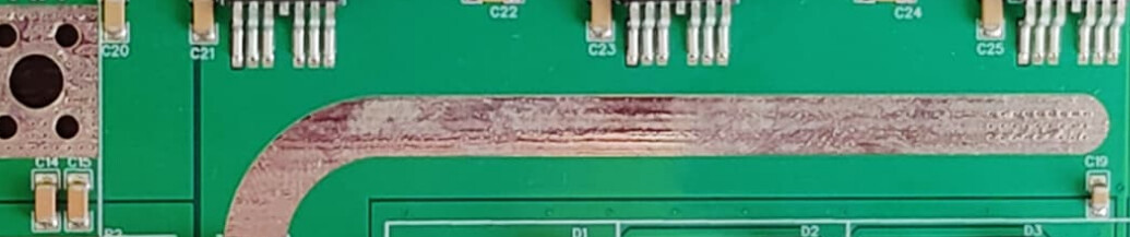
Adding solder traces during SMD by exposing the copper with a solder mask is a cheap hobby trick. Production grade thick copper layers are really expensive, like, the qvadrans will cost from 14 to probably around $30 per PCB if you only double the thickness. If you want even higher current, for example production grade 6oz copper, the PCB alone will cost you $100 in China, and about $1000 in USA. Per each PCB. A batch of 5 small motor driver PCBs in USA house cost easily 5 grand.
For example, the Krakatoa has exposed solder mask for thickening of the current trace.
Neat, I’ve never heard of smd links, but I have thought it would be nice to have solid copper pieces on a pick-and-place machine. Does LCSC carry them? I’m not sure what category to look in.
You can solder on pieces of copper to boost current capacity, but most of the time there will still be pinch points where the PCB copper has to carry the full current, like between the mosfets and current sensors, and between sensors and wire terminals.
The dual-channel mosfets used on Lepton give a unique possibility to almost entirely eliminate pinch points, because the high and low side both share the same output pins so you can solder the motor wire directly to them. I took advantage of this on my variant of the design https://community.simplefoc.com/t/lepton-deku-mod/2641/55
I’ve been trying to come up with a good construction process for higher powered drivers using machined copper pieces to eliminate the PCB entirely in the high power section. But even without current sense, you have to get 9 signal lines across the boundary to the low voltage section (two gates and the floating supply return for each phase).
Another potential approach is to design a board where the high power area is left as an incomplete expanse of copper. Solder a thick copper sheet over it, machine traces in it, and solder mosfets and current sensors on top. It would require precise registration so your machined traces meet the etched traces and vias on the board, but that should be doable. The machining could most likely be done using Paul McClay’s Minamil
EDIT: Random idea for improving conductivity in small pinch points where it’s impractical to use solid copper pieces: Mix copper powder with solder paste. Tin has about 7x the resistance of copper, so if solder flooding doubles the conductivity, replacing half of it with copper particles should give about 4.5x. I’ll see if I can grind up enough to do some testing.