I have been unable to actually find any sources for similar smd links to the ones used in the inverter. I guess they are a custom thing.
You could also order some copper cut out by SendCutSend. You’d need to tile the part kind like you do with PCBs and they have a minimum of a $30 order but it could be a decent option for a medium run of boards.
Personally I’d plan to make a through hole at each end of the track and install a peice or two wire.
I did find a few threads on the eevblog forum going into detail about using plain solder. Apparently it’s common on power supplies and one user found it increased the current carrying capacity by about 40%.
I found some 350 mesh copper powder ‘For cold casting’ on amazon. 1lbs for about $20
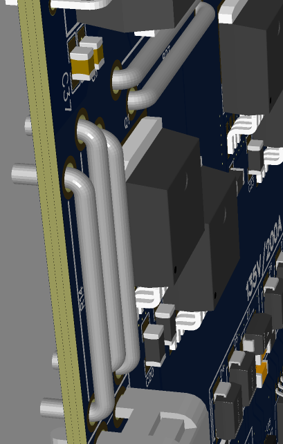
Please pay attention how I solved the high current using shunts effectively opening up another high current layer as shunt bridges. JLC will solder those for you.
Thanks! I found them on page 3 of search results for “copper shunt”. All the part numbers start with JW, like JW105X19X5, so sorting alphabetically might help pick them out of the 76000 total results. I just got lucky that they showed up near the top. Looks like they’re sold as current sense resistors, and come in many different lengths. And they’re practically free.
That’s a good idea. If machining more complex copper pieces before assembly, the wires would double as position pins to ensure that the copper pieces don’t shift around when soldering.
Yeah, I found that too. Almost bought it, but then occurred to me that I can find out if it works without waiting or spending any money Took a few minutes of sanding a scrap of copper pipe on a coarse sanding belt, but I’ve got a little pile of copper dust to play with now.
LOL yeah, so get the one with the least resistance.
I avoid soldering those thick wires manually, the copper plates suck the heat really fast and it requires a really powerful hot plate/hot air and special solder gun. JLC uses wave soldering. Save your lungs and eyes and fingers, they are worth a lot more than a few pieces of copper.
Personally I recommend being careful with JLC’s wave soldering service, I used it to assemble the connectors on my motor driver board, and ended up with big solder balls on some of the pins, and the solder did not fill the hole properly, leading to a bad electrical connection to inner layers.
My board is 6 layers with 2oz copper on all layers, and is designed so the PCB acts like a heatsink. It was probably too much for the wave soldering service. In the end I had to rework the solder joints myself, by using a hot air station to heat the board while using a soldering iron to fix the solder joints.
Yeah, it might still be worth more experimentation. I ended up sleeping after grinding the dust and before running the tests, so it was more oxidized than it could have been. But the paste has so much flux in it, I doubt that’s the problem.
Could try stirring it while it’s melted, but even if it works, it would only be doable in open areas where solid copper is better. I was hoping to use it for tight spots.
Contamination from the sanding belt is a possibility. I’d like to try with commercially produced high purity dust, but my guess is it will do the same thing, so I don’t want to spend the money.
My dust was fairly large/coarse, but if anything I’d expect finer dust to be worse since it has more surface area to oxidize.
I have built a DC (brushed) motor controller and needed higher current than the small trace woud allow. The solution was to get some 10 AWG solid coper wire and bend it to exactly follow the PCB trace, with minimal airgaps. Then I hand solder the wire to the traces. It can handle at least 30A with no detectable heating.
You would never do this on a comercial design because of the labor cost to hand-build the product. If I needed 100A I would go with square cross section copper bar stock and design the PCB to not have bends
I have also made my own treminal connectors by drilling a 3 or 4 mm hole in the PCB and using a brass screw and nut. I torque it down then hand solder the screw and nut being carful to not get solder in the exposed threads above the nut. Now I have a threaded stud connector for a crimpped-on ring terminal. Again, to much hand labor for a comercial product.
I had the current set a good bit higher than I meant to and had a nice little smoke plume a few seconds after powering on.
I made sure the plug to my power supply was easily accessible and I had a place to throw things in case of a fire. I’ve set up a proper emergency power kill for when this happens again.