135V / 200A ESC Krakatoa

Well, this is the setup. Good news that it works. Bad news is that it blew up my power supply. Next step is to test with a 1000A lead acid battery. Pencil for the wire thickness comparison. In a few hours, if you hear a loud cataclysmic explosion, that’s the Krakatoa board blowing up.

Oh yeah and buy a new PS…

The test was successful. I discovered a number of small problems and had to rework the design to make it user friendly. The Infineon driver is not exactly what you call user friendly so I had to add some friendliness. Downside is it made it more expensive and complex.

Modified driver is in the link above on that thread. Below is just a screengrab of the 3d render.

3 Likes

For those of you who noticed I changed the design again. At very high drain voltage and current the IR cannot deliver the gate current required to open the gates and overheats. The mosfets I chose are made of very cheap chinesium and have extremely high gate charge. Plus I proved the IR works and moving on to improve my designs. This is not a real production pcb, this board is a test and experimentation setup for me. Who knows, tomorrow I may reject the dgd drivers, too, and rework it again with yet another driver.

Omnia mutantur, nos et mutamur in illis;
Illa vices quasdam res habet, illa vices;
Quo modo? Fit semper tempore melior homo.

Cheers,
Valentine

Valentine, I really appreciate you posting your controller designs! I was able to learn quite a lot from studying your layouts.

Regarding the ITRIP, would you give a little more explanation? I searched Itrip on the rest of the forum and searched on the Docs without much success. Maybe I missed something simple in the documentation.

itrip is the driver trip current. it causes the voltage drop across the sense resistor to exceed the trip level, iirc 0.4V. thank you for liking my designs, hope im helping here. cheers!

@Kai_Justice

Please refer to the documentation.

Cheers,
Valentine

@Valentine

Aha! Thank you, this makes more sense when considering the Infineon driver chip. A hardware safety is a great feature.

It appears that you moved away from this chip in leu of the DGD2110S16-13. The schematic in easyEDA shows both. But the hardware layout has the DGD2110S16-13. This is then routed to the micro to make a determination to shut off the 3 mosfet drivers?

I appreciate your explanations,


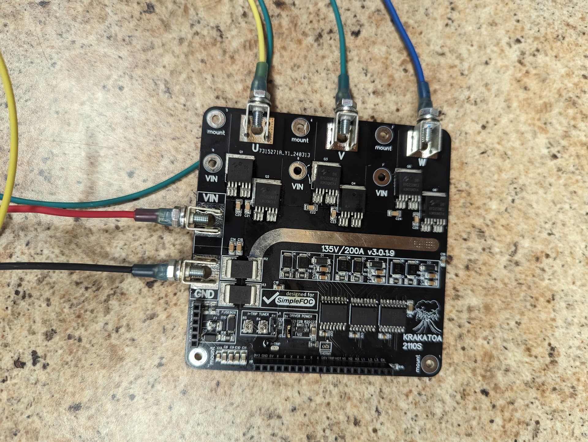
Continuing to use this board to learn from.
(Note the 3 amp fuse).

I am not quite sure what to expect out of the drivers.

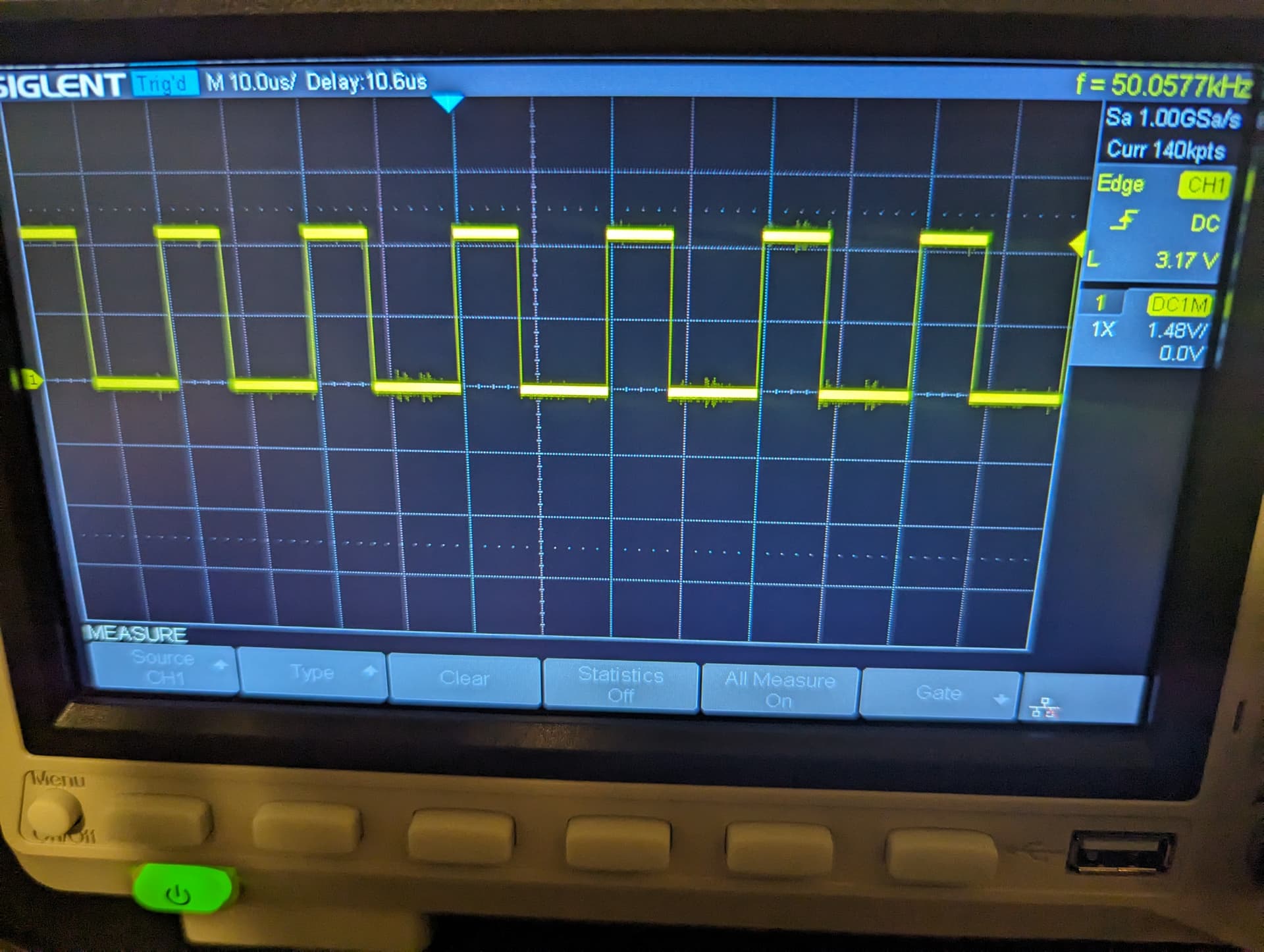
I have the open loop velocity example loaded up and have square waves present on the appropriate pins ( B13-A10), 12v present on c17, c12, c1. I expected to see some square waves on the outputs of the drivers.

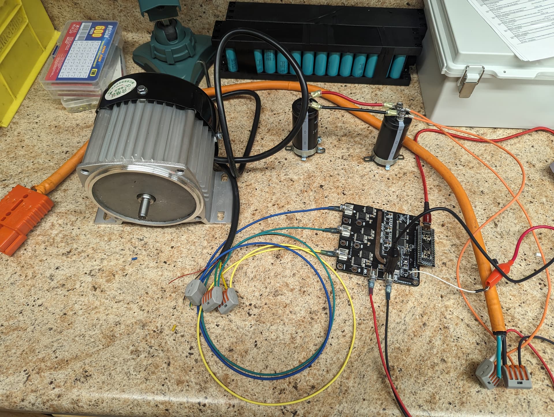
I added capacitance and the motor to see if maybe if I was misunderstanding a signal and needed some inductance or a load, this did not make a difference.

Mosfet pins are not shorted… Maybe I ruined the driver chips while soldering…?

12v present on R1, R10, and R12…

Common grounds between 3.3v and 12v supply… I do have a 48v battery hooked up. But my belief is I should see output waveforms without this.

Any pointers?

2 Likes

@Kai_Justice

Im traveling and my access is limited.

Amazing Setup, will look into it when i get the right time

Meanwhile please post your open velocity code.

Also i see you replaced the drivers, schematics of the PCB will be very helpful, probably necessary.

Cheers,
Valentine

@Valentine hopefully you are traveling somewhere warm! It has been raining nonstop and threatens snow again here in Northern Indiana.

I hope I did not replace the drivers, I followed the schematic from the link a the top of the post;

// Open loop motor control example
#include <SimpleFOC.h>

// BLDC motor & driver instance
// BLDCMotor motor = BLDCMotor(pole pair number);
BLDCMotor motor = BLDCMotor(4);
// BLDCDriver3PWM driver = BLDCDriver3PWM(pwmA, pwmB, pwmC, Enable(optional));
//BLDCDriver3PWM driver = BLDCDriver3PWM(PB1, PB0, PA6, PA7);
BLDCDriver6PWM driver = BLDCDriver6PWM(PA8, PB13, PA9, PB14, PA10, PB15, PB12);

// Stepper motor & driver instance
//StepperMotor motor = StepperMotor(50);
//StepperDriver4PWM driver = StepperDriver4PWM(9, 5, 10, 6, 8);

//target variable
float target_velocity = 0;

// instantiate the commander
Commander command = Commander(Serial);
void doTarget(char* cmd) { command.scalar(&target_velocity, cmd); }
void doLimit(char* cmd) { command.scalar(&motor.voltage_limit, cmd); }

void setup() {

// driver config
// power supply voltage [V]
driver.voltage_power_supply = 58;
// limit the maximal dc voltage the driver can set
// as a protection measure for the low-resistance motors
// this value is fixed on startup
driver.voltage_limit = 48;
driver.init();
// link the motor and the driver
motor.linkDriver(&driver);

// limiting motor movements
// limit the voltage to be set to the motor
// start very low for high resistance motors
// current = voltage / resistance, so try to be well under 1Amp
motor.voltage_limit = 58; // [V]
// open loop control config
motor.controller = MotionControlType::velocity_openloop;

// init motor hardware
motor.init();

// add target command T
command.add('T', doTarget, "target velocity");
command.add('L', doLimit, "voltage limit");

Serial.begin(115200);
Serial.println("Motor ready!");
Serial.println("Set target velocity [rad/s]");
_delay(1000);
}

void loop() {

// open loop velocity movement
// using motor.voltage_limit and motor.velocity_limit
// to turn the motor "backwards", just set a negative target_velocity
motor.move(3);

// user communication
command.run();
Serial.println(target_velocity);

}

At one point I just set the velocity to 3 such that I did not have to rely on the commander serial interface. I have also tried 5 rad/s.

A few more photos. I wanted to show the waves making it to the driver chip and then show waveforms not coming out of the driver chip.


I am going to draw out the driver and confirm signals on all pins to see if something comes to mind.

Hey, quick one, I’m n the road but before you start “drawing out” things, this driver has reverse shutdown logic. Low is enable, high is disable. Did you properly enable the driver in the code?

Please carefully read the documentation

Page 5

In your code I believe you got it reversed so you shut down explicitly the driver.

Check what’s the signal going into the SD pin, it has to be low. If it’s high (3.3V) you are shutting it down and the driver is in sleep. If you read the doc, the pin is called “shutdown”, not “enable” so HIGH is SHUTDOWN (sleep), LOW is ENABLE, ha ha.

There was an option in SimpleFOC to trigger reverse enable logic. Let me check what was it.

Cheers,
Valentine

PS OK found it.

driver.enable_active_high = false; // Reverse logic driver, low is enable
driver.init();

Before you init the driver please reverse the enable logic. And please, please read the documentation :slight_smile:

I even tied the enable LOW be default with a pulldown resistor.

If you remove B12 from the init, I believe this would default the driver to ENABLE even without the reverse logic directive.

Aha! Thank you for the direction! I changed the line of code and now have the logic reversed.

Still no output from the driver chip, even when I verify the logic diagram as shown and the data sheet and as you posted above.

I may try to take the 2nd board and populate a single driver. Really wondering if I damaged the chips somewhere along the way.

I did try 20k and 10k to see if maybe I had some sort of noise due to a higher frequency. This was little far fetched, but It was easy enough to attempt.

I did verify that all 3 chips act the same. I popped out the stm32 and pinned in only 1 one of the driver chips with the same result. Also tried tried running a ground directly to the SD pin.

That’s way way too high.
In openloop velocity mode, that’s the voltage you are driving the motor with.

If the voltage supply is about 60V, yes that’s a little (too) high, I would probably lower it to around 10V for a test run. However this is not preventing the PWM from triggering the high/low driver gates signals.

There has to be a different reason.

Valentine

I took the step to attempt at looking at just the driver. I lowered the voltage as suggested!

When gnd, 3.3v, and 12.2v are applied to the power pins on the board, the H0 pin reads near 0.

When the power supply to the VIN is applied (14 volts), the H0 pin jumps to 10.46 volts. The enable pins are held at about 11.5v. Vcc held at 11.5.

image
image

// Open loop motor control example

#include <SimpleFOC.h>


// BLDCDriver3PWM driver = BLDCDriver3PWM(pwmA, pwmB, pwmC, Enable(optional));
BLDCDriver6PWM driver = BLDCDriver6PWM(PA8, PB13, PA9, PB14, PA10, PB15, PB12);

void setup() {

// driver config
driver.pwm_frequency = 20000;
// power supply voltage [V]
driver.voltage_power_supply = 12;
// limit the maximal dc voltage the driver can set
// as a protection measure for the low-resistance motors
// this value is fixed on startup
driver.voltage_limit = 16;


driver.enable_active_high = false; // Reverse logic driver, low is enable
driver.init();

//enable driver
driver.enable();
_delay(1000);
}

void loop() {


   // setting pwm (A: 3V, B: 1V, C: 5V)
    driver.setPwm(3,1,5);
    delay(1);
}

I will try to review and check your input, cheers, Valentine.

Last night, I did try running a single chip with inputs and worked to observe the outputs. I found the same results as the entire board… Consistency is good. But still the incorrect result.

I am excited to learn what I am doing wrong.
Part of my misunderstanding is what I should be seeing on the output pins… I believe I should see a similar square wave as the input.

@Kai_Justice

Correct. Still seems the driver goes to shutdown mode but not sure why. Needs investigation.
Are you in continental US? PM/DM me please.

Cheers,
Valentine

The board logic requires 12V. The bluepill puts out 3.3V.

I modified the board to use 3.3V and also added some extra stuff.

The board is complex enough to require documentation, so that’s the main issue.

I tested, it works. New release is on the OSHW.

Also please note this driver is reverse logic, enable low, disable high.

Cheers,
Valentine

1 Like