Hi Andrew , Hi Antun , all
thx for you interest, regardfullness, and work…
@Antun… funny, I studied microelectronics at IXL lab … 30y ago… almost neighbour
OK, then, this topic is spin off from this one => Is it possible to use inverted low input with simple foc? - #26 by iso14000
I played a few month ago with the almost “out of the box” software from M. Feru (and others) for hoverboard… it was fun and wanted to dive a little more on this fascinating project…
I’m an electronics, and of course bad in C and worst in C++.
The actual hardware is 99% genuine from a onewheel (buyed on a famous french peer to peer plateform for a ridiculous price)
I’m sure the hardware is working, because before tinkering with it, the device was working OK, quietly .. do for me it is a good starting point.
After struggling with some code , I ‘ve got a wheel spinning , noisy.. good
What is the driver you’re using, I suppose it’s not the original onewheel driver?
on the contrary… it is the genuine one!
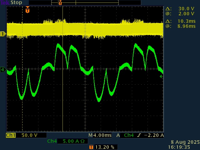
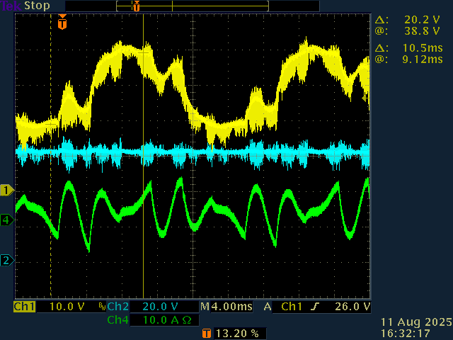
Where are you measuring this current, it looks more like the power supply current than the phase current… 
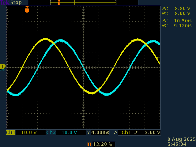
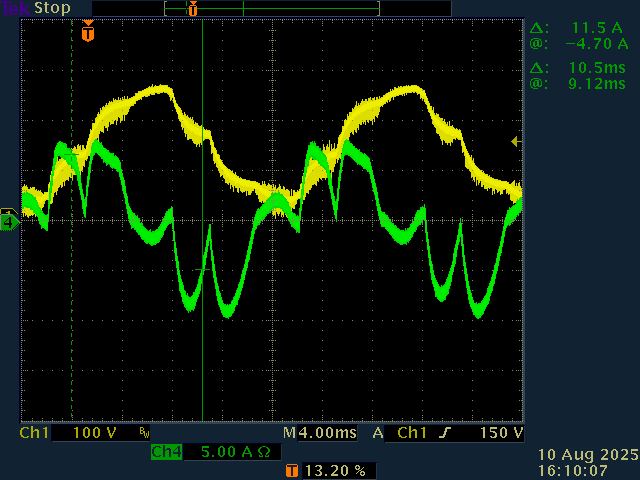
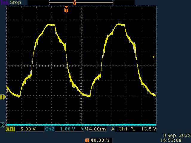
the current is measured with a current clamp (green), on the same branch that provides voltage (yellow).
Of is it the current measured across the low-side shunt (plus some filtering) ?
there is no shunt on this board, current is measured across Mosfet Drain to source voltage and added to an offset , and finally a small gain is applied.
The only shunt available was a 3.5 mR , but the latter make a sum of all three branchs current, I guess it is used as an emergency stop in case of catastrophic failure. Actually this shunt is deactivated becasue library doesn’t handle it (afaik) .
f you’re really motivated you could take one of your 10mOhm resistors and put it in series with one of the phases of the motor and measure the current directly on it.
my probe do that nicely 
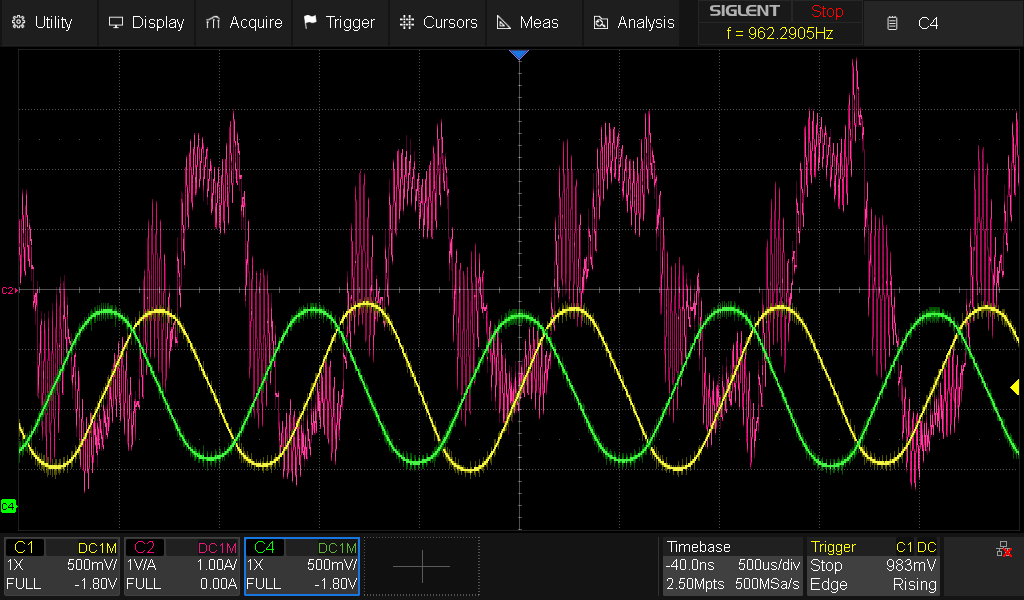
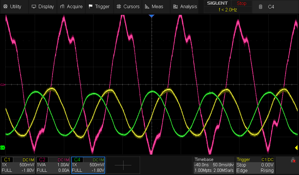
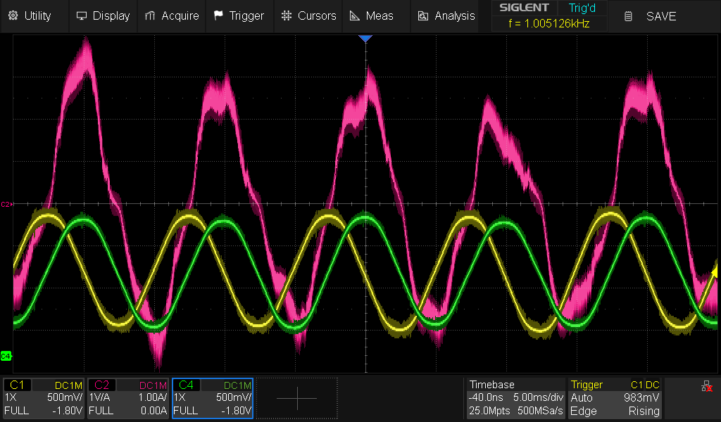
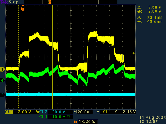
I have noticed in your screenshot of your filtered waveform that the phase voltage seems to rise compared to a perfect sine wave when the current is positive, and fall when the current is negative. I think this points towards a high wiring resistance, or a too long dead time.
wiring is the genuine one, far from perfection of course, but it is very short, I have to remove my hand from the mouse to not be injured by the wheel when it starts spinning.
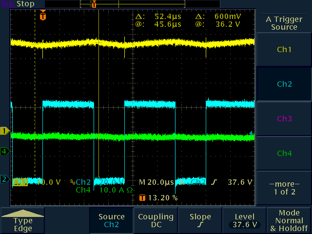
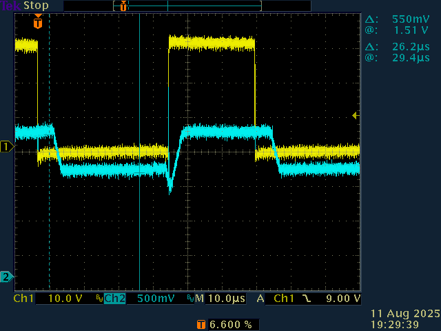
Could you measure the supply rails on the input of the driver board while the motor is running, as well as the output voltage without the filter, showing a single PWM cycle? This way we can check for any unusual voltage drops, and check whether the distortion is caused by the dead time.
I will , so with sweep time about 10xf0 (here f0 is around 20Khz)
Another theory is that the position sensor is not very accurate, so the inaccuracies cause the FOC computations to be off, resulting in weird current shapes.
as I said, hardware is 99% genuine, (emergency shunt deactivated)
thx for your advices