Conclusions from the latest testing:
- Capacitors don’t help with voltage spikes.
- What does help is ramping velocity to avoid applying torque in opposition to motion.
- Voltage limit > 6.5 causes skipping (maybe CPU speed?)
- Flux observer is giving me wonky current waveforms.
- 2 current sensors is all you need.
- The default current PID values are good.
- Actual no-load RPM is ~1.5x motor voltage x kv. This means you can only reach 87% of power supply voltage x kv, even with SpaceVectorPWM.
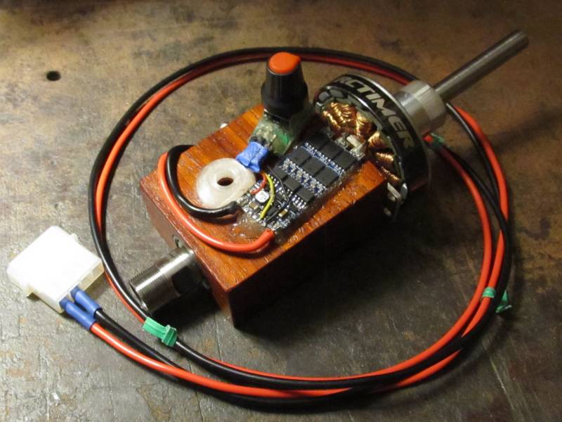
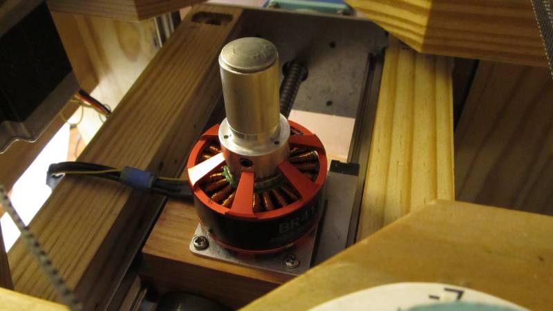
Now that my milling machine has Gooser5, I put its old B-G431B-ESC1 on my lathe toolpost mini-spindle, which has a modified RCTimer 5010.
It had even more trouble with voltage spikes shutting off the power supply than Gooser5, which is surprising since I never had any trouble with it on the mill with its larger Racerstar BR4114. Maybe because the mini-spindle’s bearings spin more freely, so the mill was dissipating energy through friction instead.
Both of them now run in torque mode with target = motor.current_limit, and use motor.voltage_limit to control speed, with changes ramped at 20V/s so it slows down gently (previously I was changing in 1V steps instantaneously). No more problems until I get above 6.5V, at which time both of them start skipping and can spike the power supply. Coincidentally the electrical RPM is about the same on both, and this is about 24 updates per electrical revolution, so that may be the minimum needed for flux observer to work.
I tested the ESC1 with and without a 2200uF capacitor, before and after adding the voltage ramping. It doesn’t seem to make any difference at all, so apparently the 210uF of onboard ceramics are all it needs. I have 330uF of ceramics on the Gooser5, so its electrolytics were probably superfluous too.
Next I set off on a campaign of current waveform plotting on the mill’s Gooser5 running Racerstar BR4114. I wanted to see how my plan to sample the two current phases farthest from their sine wave peak compares to sampling all 3 phases, or only having 2 current sensors. The shape of the waves is nearly identical in all cases. Dynamically selected phases is actually the worst because it introduces a small spike at each sector change, although this may disappear with amplitude calibration. When running open loop at 30rad/s, my phase A sensor is giving ±10.8A, phase B ±10A, and phase C ±9.8A.
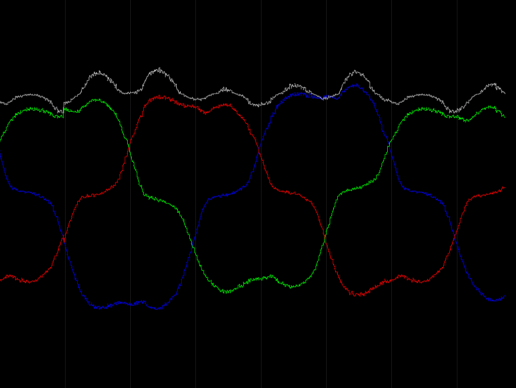
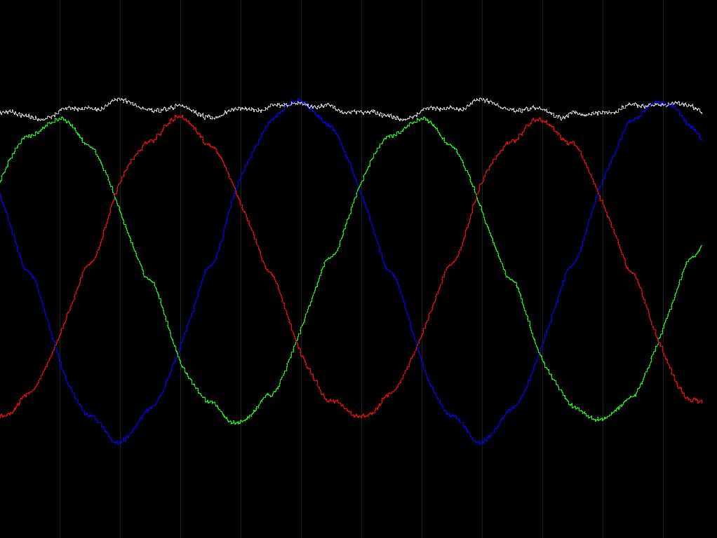
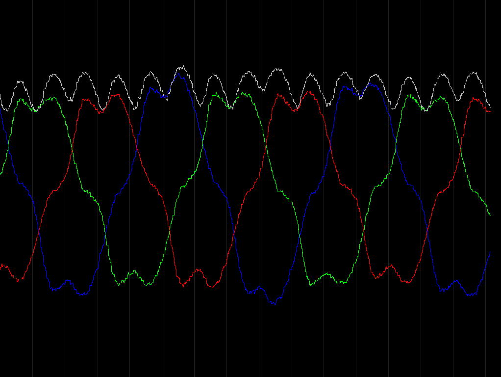
Open loop gives fairly clean waveforms. 20rad/s is trapezoidal (ignore the artifact at the first vertical line), 30rad/s sinusoidal, and 50rad/s looks like the SpaceVectorPWM waveform, but gets the same thing when running with sine modulation so I’m not sure what that’s about. It’s possible the shape is affected by the balance between speed and voltage limit, but I didn’t think to test it at the time.
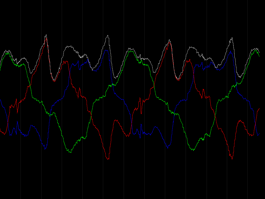
The dark gray vertical lines are 60 degree boundaries, blue is phase A, green phase B, red phase C, and light gray is currentSense.getDCCurrent().
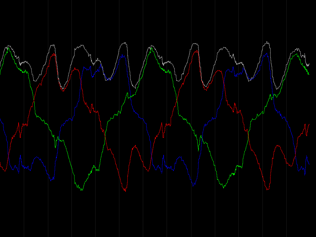
And here are the wonky waveforms of closed-loop flux observer running at 35rad/s and 100rad/s. 100rad/s is hard to even see the fundamental frequency anymore, yet it runs fine up to 430rad/s. Not sure what to make of this. I’m fairly certain it’s not due to my noisy current sensors since it’s so consistent. I also tried 16x oversampling compared to 64x on these plots, and it only added a bit of high frequency noise, no change to the wave shapes. I also tried playing with the current PID values and wasn’t able to improve it. I’d like to see what it looks like with a position sensor, but I don’t care quite enough to set it up. I’ll test that on the lathe’s hoverboard motor when I get a Gooser5 on it.
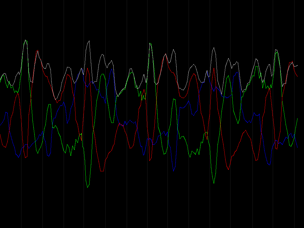
And for comparison, here is 35rad/s with sensor C disabled. As you can see, the red wave shape calculated from the other two is nearly identical to the measured one above.