it was alreay set to :
 // dead_zone [0,1] - default 0.02f - 2%
  driver.dead_zone = 0.01f;
puzzled ![]()
it was alreay set to :
// dead_zone [0,1] - default 0.02f - 2%
driver.dead_zone = 0.01f;
puzzled ![]()
is the distortion a result of the motor or the analog signal processing?
Have you tested the analog part seperately? How does the waveform change at twice the velocity or half the velocity?
the motor isn’t connected,
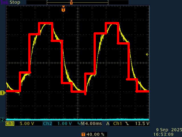
what you are seing is the output of my RC filter that integrate PWM signal from one phase.
Could it be that you’re not calling runfoc often enough? It looks like the PWM is changing as shown by the red curve, and is just being smoothed out by your RC filter.
Edit: Or maybe you’re doing close-loop control with only hall sensor (so 6 steps?)
That’s also along the lines I was thinking - if we run the motor at different speeds we should see if the pattern is to do with the sampling or the motor…
And we see the curve of the RC filter in each of the segments I think? What’s the cutoff of this filter, what components were used?
And note also that even if you run the FOC loop faster, due to the nature of Halls the sensor value would only update 6x per eRev… you could try our smoothing sensor to interpolate between the the hall positions, which would work well when the load is constant…
the main loop is only fed by three lines … pasted from example online
could you explain your theory…. it sounds interesting
If you are doing close loop control foc the pwm depend on the rotor position. If the position resolution if low, you will only update the pwm phase value based on it (hall sensors = 6 steps per electrical angle. This is what I think is causing the steps in your measurements. As @runger is pointing, if you are working at rather constant speed you could improve it by having some sort of extrapolation of the position based of the current speed, increasing the resolution. Maybe this is implemented in the lib?
For your tests you could also witch to open loop control, where the pwm phase is only a function of integrated speed reference.
I’m not very familiar with simple foc, I just wanted to point out what I saw in your scope measurements.
with all my respect fc= 1/(2pi RC) =>160hz … so it is a rather “low pass”
![]() hue?! …. I believed (like a child to santa cruz) I should see a sinus out there…
hue?! …. I believed (like a child to santa cruz) I should see a sinus out there…
I’m definetly not able to code that ![]()
I will try open loop this we
best regards
as per requested by thomasfla , I recompiled code with
// set motion control loop to be used
  motor.torque_controller = TorqueControlType::voltage; //voltage  dc_current foc_current
 // motor.controller = MotionControlType::torque;
  motor.controller = MotionControlType::velocity_openloop; //torque velocity angle velocity_openloop angle_openloop
  motor.foc_modulation=FOCModulationType::SinePWM; // SinePWM  SpaceVectorPWM Trapezoid_120 Trapezoid_150
velocity_openloop.
I have to disconnect motor windings, otherwise it hums and vibrates so much that my bench will be dismantled.
so I rotate it manually to freeze the bellow trace :
best regards
If you need to rotate manually your motor shaft to get this output pwm trace, it probably isn’t configure in open loop. Can you check Velocity Open-Loop | Arduino-FOC ? Or provide full code?
hi
herebellow the full code
//V0.7 same with motor.torque_controller = TorqueControlType::foc_current; motor.controller = MotionControlType::torque; (Screenshot 10/08 21:20:32)
//V0.8 same with 60V input, current limitation for motor and velocity speed limit
//in progress , current sense removed , sensor align removed, ... weird voltage patern anyway...
#define SIMPLEFOC_PWM_LOWSIDE_ACTIVE_HIGH false
#include <SimpleFOC.h>
//platform STM32F103C8T6
//with MPU6050
HardwareSerial SerialDebug(USART3);
int polePairs = 22; //seems OK with my motor
#define ENC_A PA0 // HallSensor A pin
#define ENC_B PA1
#define ENC_C PA2
#define LED_1 PA15
#define LED_2 PB4
#define LED_3 PB5
#define LED_4 PB8
int leds[] = { LED_1, LED_2, LED_3, LED_4 };
u_int16_t loopCount;
// Hall sensor instance
// HallSensor(int hallA, int hallB , int hallC, int pp)
// - hallA, hallB, hallC - HallSensor A, B and C pins
// - pp - pole pairs
HallSensor sensor = HallSensor(ENC_A, ENC_B, ENC_C, polePairs);
// BLDCMotor(int pp, float R = NOT_SET, float KV = NOT_SET, float L = NOT_SET);
//actual motor is star wired. R=0.25 ohm L=6mH, KV tested with the example in library=1
BLDCMotor motor = BLDCMotor(polePairs,0.25,1.00,0.006);
//BLDCMotor motor = BLDCMotor(polePairs);
//BLDCDriver6PWM(int phA_h,int phA_l,int phB_h,int phB_l,int phC_h,int phC_l, int en = NOT_SET);
//on my board PB12 is the overcurrent stop...
BLDCDriver6PWM driver = BLDCDriver6PWM(PA8, PB13, PA9, PB14, PA10, PB15, NOT_SET); //strangely fit my board! FSI
// LowsideCurrentSense constructor
// - shunt_resistor - shunt resistor value
// - gain - current-sense op-amp gain
// - phA - A phase adc pin
// - phB - B phase adc pin
// - phC - C phase adc pin (optional)
//removed LowsideCurrentSense current_sense = LowsideCurrentSense(0.009,-2.7, PA6, PB0,PB1 );
// Interrupt routine intialisation
// channel A and B callbacks
void doA() { sensor.handleA(); }
void doB() { sensor.handleB(); }
void doC() { sensor.handleC(); }
void setup()
{
char i;
pinMode(LED_1, OUTPUT);
pinMode(LED_2,OUTPUT);
pinMode(LED_3,OUTPUT);
pinMode(LED_4,OUTPUT);
for ( i=0;i<4;i++) digitalWrite(leds[i], HIGH);
for ( char j=0;j<10;j++)
{
for ( i=0;i<4;i++)
{
digitalWrite(leds[i], LOW);
_delay(25);
digitalWrite(leds[i], HIGH);
_delay(25);
}
}
SerialDebug.begin(115200);
SerialDebug.println("hello word rev 0.9");
SimpleFOCDebug::enable(&SerialDebug);
// use internal pullups
//sensor.pullup = Pullup::USE_INTERN; //2.2K external
sensor.pullup = Pullup::USE_EXTERN;
sensor.init();
sensor.velocity_max = 100; //largely above 50Km/h
sensor.enableInterrupts(doA, doB, doC);
// link the motor to the sensor
motor.linkSensor(&sensor);
// pwm frequency to be used [Hz]
// for atmega328 fixed to 32kHz
// esp32/stm32/teensy configurable
driver.pwm_frequency = 15000;
// power supply voltage [V]
driver.voltage_power_supply = 20;
// Max DC voltage allowed - default voltage_power_supply
driver.voltage_limit = 20;
// dead_zone [0,1] - default 0.02f - 2%
driver.dead_zone = 0.01f;
// aligning voltage
motor.sensor_direction=CW; //okay I now the direction
//motor.voltage_sensor_align = 4;
//motor.current_limit=0.2;
// driver init
if (!driver.init()){
SerialDebug.println("Driver init failed!");
return;
}
// link the motor and the driver
motor.linkDriver(&driver);
// link driver to cs
// current_sense.linkDriver(&driver);
// init motor hardware
if(!motor.init()){
SerialDebug.println("Motor init failed!");
return;
}
/*
// current sense init
if(!current_sense.init()){
SerialDebug.println("Current sense init failed!");
return;
}
else SerialDebug.println("Current sense init success");
// link the current sense to the motor
motor.linkCurrentSense(¤t_sense);
*/
// set motion control loop to be used
motor.torque_controller = TorqueControlType::voltage; //voltage dc_current foc_current
// motor.controller = MotionControlType::torque;
motor.controller = MotionControlType::torque; //torque velocity angle velocity_openloop angle_openloop
motor.foc_modulation=FOCModulationType::SinePWM; // SinePWM SpaceVectorPWM Trapezoid_120 Trapezoid_150
// use monitoring with serial
// comment out if not needed
motor.useMonitoring(SerialDebug);
motor.motion_downsample= 1000; // set downsampling can be even more > 100
motor.monitor_variables = _MON_VEL |_MON_TARGET; // set monitoring of velocity
motor.velocity_limit=10;
motor.current_limit=3;
// align sensor and start FOC
if(!motor.initFOC()){
SerialDebug.println("FOC init failed!");
return;
}
// set the initial motor target
motor.target =5; //
SerialDebug.println("P=");
SerialDebug.print(motor.PID_velocity.P) ;
SerialDebug.println("\n\r I=");
SerialDebug.print(motor.PID_velocity.I) ;
SerialDebug.println("\n\r D=");
SerialDebug.print(motor.PID_velocity.D) ;
// motor.PID_velocity.P=100; //P gain was 0.5, with this it less abrupt during transistion
// motor.PID_velocity.I=10; // I gain was 10
// motor.PID_velocity.D=;
_delay(1000);
}
void loop()
{
/*
if (loopCount++ >=100){
loopCount=0;
if (motor.target<40) motor.target=motor.target+0.01;
}*/
//________normal section
// main FOC algorithm function
motor.loopFOC();
// Motion control function
motor.move();
// display the currents
motor.monitor();
//________end normal section
}
I disconnected the motor windings because its behaviour is dangerous : it hums and heavyly vibrates on my bench
It is unusual for open loop to vibrate, but it may be due to the hall sensor not giving a good velocity reading at low speed. Open loop mode does not look at the hardware current sense at all, but it does use voltage-based current limiting, which estimates back EMF from the velocity and kv.
Try not linking the sensor (in which case shaft_velocity will just be equal to target, rather than updated from the sensor in motor.move) and/or not providing the resistance and kv (in which case it will apply the full motor.voltage_limit, so set it to 0.25 or less to keep the current under 1 amp)
Do try the smoothing sensor in closed loop mode. Include SimpleFOCDrivers.h and encoders/smoothing/SmoothingSensor.h and declare it like SmoothingSensor smooth(sensor, motor); Then you can call motor.linkSensor with &smooth or &sensor at any time to see the difference.
It uses velocity to extrapolate the position between hall state changes, so it is also subject to the problem of jumpy velocity readings at low speed. Increasing the lowpass time constant helps. Try motor.LPF_velocity.Tf = 0.02f;
the hardware (wheel and electronic) comes from a onewheel gyro, ‘before’ I use it as a “bench for newbee” it was smooth.
so the issue now is the chair/keyboard interface :@)
I will do that.
so… I “disconnected hall sensor in the software by commented out :
// motor.linkSensor(&sensor);
and for sure :
motor.controller = MotionControlType::velocity_openloop;
abd because :
motor.monitor_variables = _MON_VEL |_MON_TARGET; // set monitoring of velocity
and
motor.target =2; //
my console nicely display both values like this : 2.0000 2.000 (so graceful!)
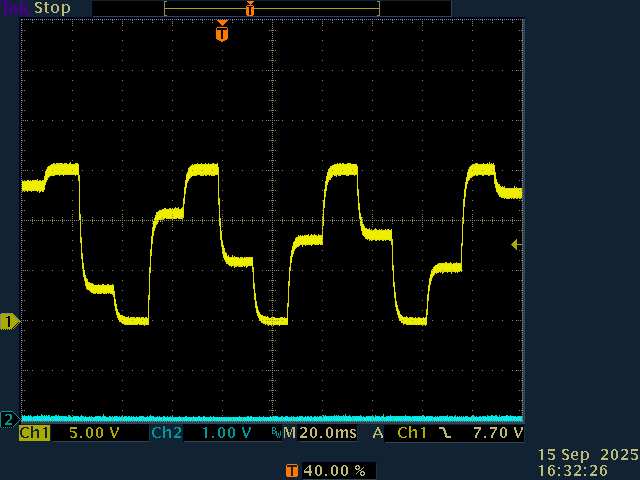
and herebellow the plot :
what does that mean…….![]()
Is this showing the current through one of the motor wires while the motor is turning slowly? If so, does the physical movement look smooth or steppy?
Assuming you have two probes, measure the voltage going to that motor wire at the same time.
for convinience , motor isn’t connected , less painfull to my ears.
it is the voltage output on one out of the three driver output.
I integrate PWM with a simple RC. (as explained above)
since almost the begining of my “knowledge ramp up” (verry steepy) with simplefoc, motor is very noisy. I finally found out why => excitation isn’t sinusoidal
finally, we , with your help, had removed all feedback and the system is blind to the sensor, this should had lead to a sinus waveform ? right?
Yes, it should be a pure sine wave. Can you remove the filter easily? The steps do look like capacitor charge/discharge curves, so maybe it’s interfering in an unexpected way.
And yes, 15KHz PWM noise is instant death ![]() Can you use 25KHz? If not, I’d drop it to 8KHz or something that’s merely irritating.
Can you use 25KHz? If not, I’d drop it to 8KHz or something that’s merely irritating.
that’s what I though also.
It is intended for. an RC filter is a in integrator, very usefull to have a good idea of a average voltage delivered by a PWM….
I can remove it very easyly, but… looking a 15Khz pwm modulated isn’t very …. usefull.
15KHz PWM noise is instant death
it is almost not audible for my ears, even the ones from my daughter aren’t able to notice it.
what is audible is the mechanical resonance, and low frequency harmonics from non sinuidal “6 steps” modulation.
a pure sine shouldn’t generate such noise.
so now, I’m in a “cul de sac” , I removed almost everything , and I still have a non-sinus modulation.
Is there a way to tinker something low level to generate that, just to have a test..
today I tried to move forward by using the “hardware brute force” …
do
    {
      delayMicroseconds (400);
      a=10+4*sin(i);
      b=10+4*sin(i+2.09);
      c=10+4*sin(i+4.18);
      driver.setPwm(a,c,b);
      i=i+0.05;
      if (i>6.28)
        i=0;

    }while(true);
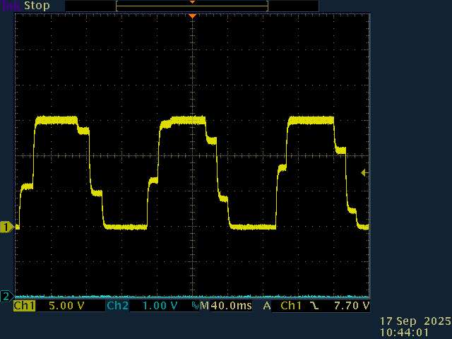
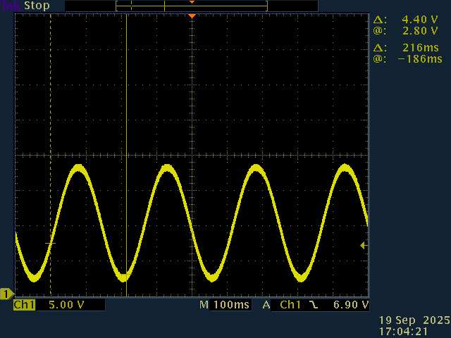
okay , it is far far away from any optimisation right… but , the wheel is turning quietly. and waveform is as follow :
that’s nicer… so I can say that … it isn’t an hardware pb,
what I did wrong ?![]()
That’s pretty much what open loop velocity does, so something weird is going on. You’ll just have to trace through the code and find where it’s going wrong.