Hello again. We took your advice and used the pins you suggested, however we’re running into new problems. The motor moves to initialize but it says that the initialization fails because it fails to notice movement. When seeing this, we ran the sensor test and it appears to be getting the hall sensor input just fine (Videos below). If the sensor test is working, why is it failing to recognize movement?
Also, we ran the driver test and got the correct voltages on each phase, so we think that our hardware is working ok.
Here’s a link of the sensor test working and the main function failing to initialize
Also, here’s the code we’re running for the main:
#include <SimpleFOC.h>
#include <Arduino.h>
///////PHASE PINS/////////
int pha_h = D1;
int pha_l = D3;
int phb_h = D0;
int phb_l = D6;
int phc_h = D9;
int phc_l = A6;
/////////HALL SENSOR PINS///////////////////
//TODO: figure out which phase is which sensor
int halla = A4;
int hallb = A3;
int hallc = A2;
int PP = 21;
BLDCDriver6PWM driver = BLDCDriver6PWM(pha_h, pha_l, phb_h, phb_l, phc_h, phc_l);
HallSensor sensor = HallSensor(halla, hallb, hallc, PP);
BLDCMotor motor = BLDCMotor(PP);
void doA(){sensor.handleA();}
void doB(){sensor.handleB();}
void doC(){sensor.handleC();}
void setup() {
Serial.begin(9600);
sensor.init();
sensor.enableInterrupts(doA, doB, doC);
driver.pwm_frequency = 20000; //Hz
driver.voltage_power_supply = 48;
driver.voltage_limit = 10;
driver.init();
motor.useMonitoring(Serial);
motor.linkSensor(&sensor);
motor.linkDriver(&driver);
motor.controller = MotionControlType::velocity;
motor.init();
motor.initFOC();
}
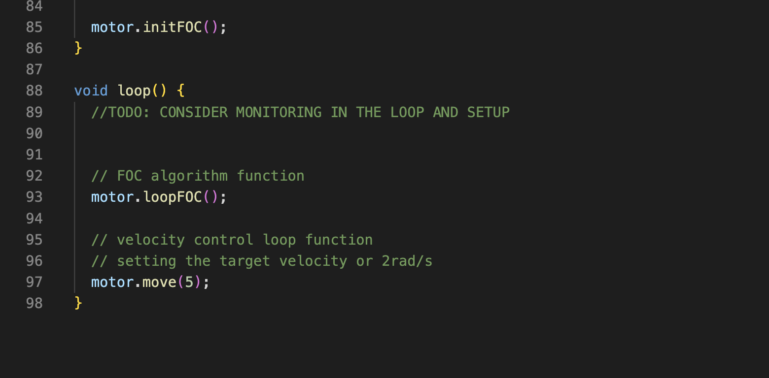
void loop() {
motor.loopFOC();
motor.monitor();
// velocity control loop function
// setting the target velocity or 2rad/s
motor.move(3);
}
thanks for your help again.