So I apologize about the video quality but what I was trying to show is it starts at zero for the angular position, then I rotated it by hand one full rotation and it ends at ~6.2 so I’m pretty sure that part is working. I also noticed in that second column when we do this it shows the velocity which appears correct as it’s positive when we spin it one direction and negative when we spin the opposite direction.
We’re looking into getting a new motor because this one that we’re using uses way too much energy to begin with:
Do you have any input on how to go about choosing another motor for our purposes? Our car is about 50-75 lbs without a driver and around 200 lbs with a driver.
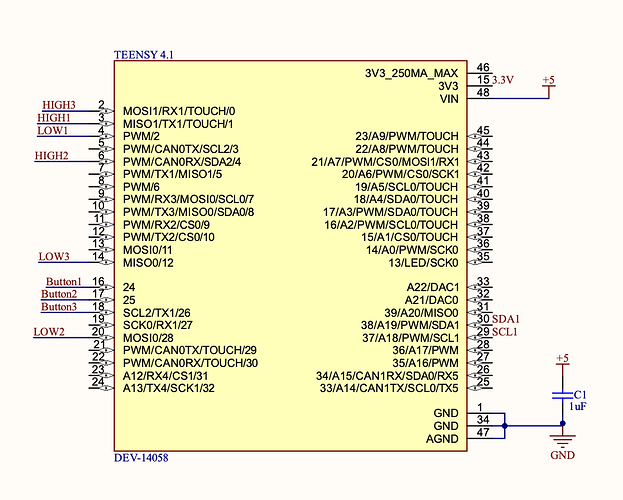
What MCU board are you using? I don’t think those look correct for an STM32.
Let’s try to run in open velocity mode first to make sure you can get the phases correctly.
Your motor (the one from the video) is not only inefficient, but hall-sensor FOC is inherently inefficient. You need a nice SPI sensored motor with a good angle sensor to achieve max FOC efficiency.
The T_Motors are nice, however.
You need to be VERY careful selecting a drone motor because those are designed to use forced air cooling from the propellers and they deliver max thrust at high RPM. If you run them slow and with passive cooling you will burn them. Let me look into some motors, What’s your budget?
I would suggest you go for a direct drive motor to avoid any complications. However, you may not have a budget for a high efficiency direct drive. I see you are using a bicycle chain.
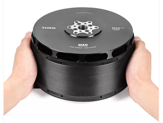
Check this one out. However, you will need a much better upgraded driver to handle that one
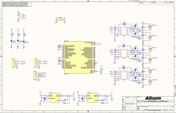
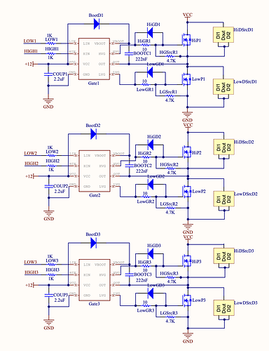
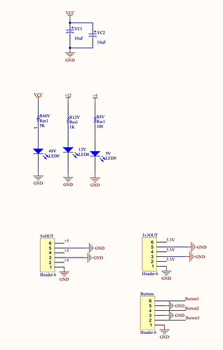
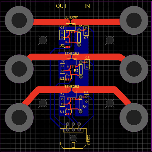
So according to the rules of the Shell Eco Marathon, we have to create our own driver board. This is our first time creating an ESC from the ground up, so I’m sure that our driver is a source of some of our problems as well. Would you be willing to take a look at our schematic and PCB files and give us any tips? We’re trying to have our first iteration ordered by this coming Sunday. Thanks so much for all your help!
So our budget for a new motor is $1,000-$1,700, but we’re looking to stay on the lower end of that. We’re currently looking into some road load equations while trying to research motors which will run optimally at the wattage that we require. Do you have any tips about how we should go about calculating this road load equation? We’ve weighed our car with our driver to be approximately 200 lbs. This is what our vehicle looks like: MAGNOLIA
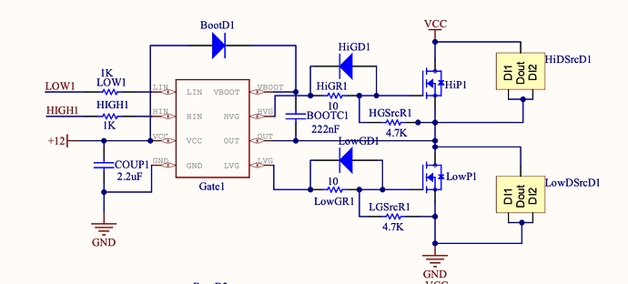
Sure, let me try. I see you got a picture but it’s really blurry. Please post a PDF or hi-rez. I cannot read the components. Also Altium doesn’t list the components, I need the BOM.
From the files you posted I see some minor problems with the schematics but nothing stands out. If you gave me the components I would be able to comment more.
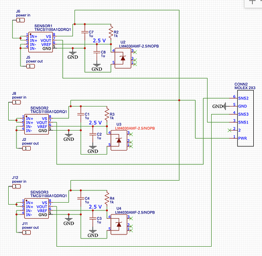
One comment, you are considering running without current sense? This will further lower the efficiency of your control loop. You will achieve best efficiency if you run closed loop with an angle sensor and current sensing.
Let me check the layout.
Looking at the layout, you need a lot of work. Separate the power output, input signal and input voltage section, use copper plates instead of traces, use thermal vias, use a lot larger mosfets, I mean, for 3 to 5kW motor you will need minimum 100A mosfets to take care if inertial loads and stay comfortably under the max continuous load. Also the larger the mosfet the lower the resistance hence the thermal losses, since you play the loss game here.
I’ll check that one too. I used to do racing and looking at the pictures that steering wheel gives me a headache. I won’t comment on the mechanical design though, haha.
Edit: Looking at the vehicle and assuming certain parameters I estimate the motor wattage required to be around 3kW. I would safely go for 5kW to stay on the safest side because the dynamic acceleration needs to be counted. Also, looking at the overall picture, definitely the motor efficiency, sensoring and drivetrain will make a very big difference on the mileage because your best case would be driver component selection, algorithm, sensoring and drivetrain. For sure direct drive will make a difference — get rid of the bicycle chain. You also need very efficient, very high quality batteries with low resistance — they sell high efficiency batteries but you need to build the pack yourself and level/manage individual cell consumption to achieve maximum efficiency drain. Have you done this before? I have so many comments I don’t know even where to begin.
A lot of my driver board designs are public, why don’t you see the way I’ve done them:
That will drain the battery way to fast! There are so many parameters to consider, but I guess those are secret? If they already use a bike chain, why not fit it with a two or three stage gearing? You could potentially interface the Teensy 4.1 (if that is your target) with a external 14/16 bit ADC, which will probably use a SPI interface with parallel datalines for highest possible throughput. That will require some hardcore coding, but is none the less possible and would contribute to a broader, pro_use of the T4.1 for BLDC purposes.
@Skylar_Lennon What is your battery capacity ?
It’s an electric car, of course that’s the whole point. A compact electric car consumes between 5 and 10kW at 35mph and the motor is rated at about 100kW. The Tesla single motor is rated at 1000kW. That’s a completely different ballgame they are playing here. The drag coefficient goes up quadratically with the speed.
Hoverboard motors are about 10kW. Think about that.
Running a 5kW motor is actually on the low side of envelope.
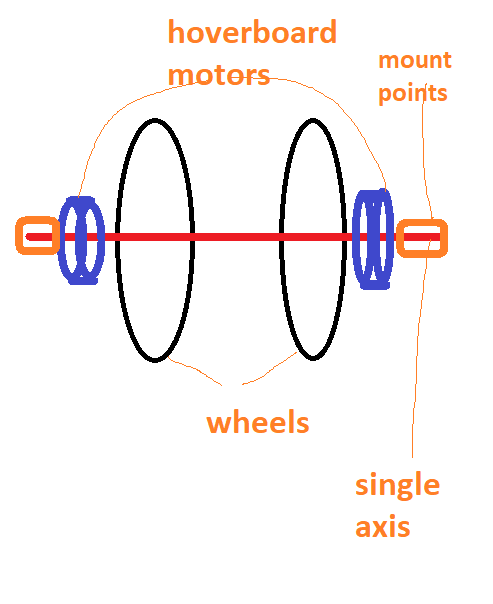
Which, aktchsually… gives me an idea. @Skylar_Lennon , why don’t you attach two hoverboard motors to each of the bicycle wheels? This will make your design so much simpler. You can hard-wire them on the same axis to run with the same board. I’ve ran two on-axis opposite field motors on one driver. I even had a video of this somewhere on the forum here.
You don’t need to use hoverboard motors you can use high efficiency low kv drone motors.
[quote=“Valentine, post:27, topic:2628”]
I see you got a picture but it’s really blurry. Please post a PDF or hi-rez.
I apologize about that. It seems like I can’t post PDF’s, so let me send you closer up screenshots.
I think we’re probably going to stick with an STM board due to time constraints, so you can ignore the Teensy 4.1 label in the schematic and those specific traces in the PCB. Also, were the PCB DOC’s blurry, or just the schematic? I can resend the others if need be.
We are actually in the process of prototyping a current sensing board right now. I can send you those documents as well.
Here is a link to our BOM, let me know if it gives you access. Also, we are definitely willing to change these components and are open to any suggestions.
That’s a lot better, however, without the exact components name/model/manufacturer and datasheets I cannot comment. Please also attach the BOM.
edit: I see you attached the BOM while I was typing let me have a look.
Google is asking me for login, any way to share this public?
If it is private please direct message me I will send you my email.
For our competition, we have to go 10 miles in 40 minutes. So we need to average 15 mph.
How do you measure the energy expended? Battery charge indicator?
We’re currently working on a board that will give us power readings from a current sensor and voltage divider. We’re trying to sort of prototype our own Joulemeter, but a Joulemeter is what they use for the competition. We have a joulemeter, but haven’t had our car working for an extended period of time to really test it out.
Could you help me find where that video is? Seems like it would be a good idea to implement two motors to our front two wheels. They could be on the same axis and coming from the same driver like you said. This would eliminate a lot of losses coming from our bicycle chain as well.
https://community.simplefoc.com/t/experimental-high-current-driver-30a/1481/39
https://community.simplefoc.com/t/experimental-high-current-driver-30a/1481/45
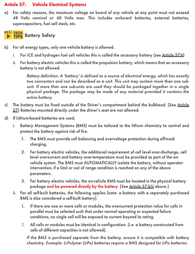
These are the rules for our competition. The battery we currently have was bought before I came on the team and I’ve had trouble finding it on the internet. This is the most similar battery I could find and it’s what we included in our BOM.
