Motor Very Fidgety During Open Loop [VID INCLUDED]

Hi everyone

We are members of a university project team at University of Michigan, and we are trying to use the SimpleFOC code to control our motor.

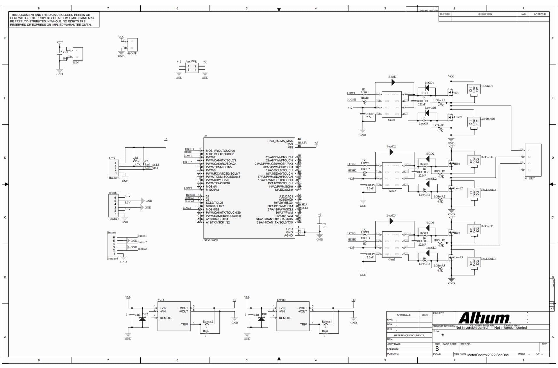
We had to build our own board to work alongside the code, since the competition we are competing in requires that we do so. Attached is a schematic of our board below:

We went through the tutorial on the website, and we were on Step 2. Testing the driver + motor combination - open-loop. We used the code shown below:

// Open loop motor control example
#include <Arduino.h>
#include <SimpleFOC.h>

///////////////////////// Pin configuration - SETUP ////////////////////////
int hallA = 10;
int hallB = 11;
int hallC = 12;

// 21 for NEW
int PP = 21;

// Phase A
// Pin 3 - FTM1 CH0
// Pin 4 - FTM1 CH1
// Phase B
// Pin 6 - FTM0 CH4
// Pin 20 - FTM0 CH5
// Phase C
// Pin 2 - FTM3 CH0
// Pin 14 - FTM3 CH1

// int phA_h = 3;
// int phA_l = 4;
// int phB_h = 6;
// int phB_l = 20;
// int phC_h = 2;
// int phC_l = 14;

////////////////////////////////////////////////////////////////////////////
// Trying different configurations

// // Config 1
// int phA_h = 3;
// int phA_l = 4;
// int phB_h = 6;
// int phB_l = 20;
// int phC_h = 2;
// int phC_l = 14;

// // Config 2
// int phA_h = 3;
// int phA_l = 4;
// int phB_h = 2;
// int phB_l = 14;
// int phC_h = 6;
// int phC_l = 20;

// // Config 3
// int phA_h = 6;
// int phA_l = 20;
// int phB_h = 3;
// int phB_l = 4;
// int phC_h = 2;
// int phC_l = 14;

// HORRIBLE
// // Config 4
// int phA_h = 2;
// int phA_l = 14;
// int phB_h = 3;
// int phB_l = 4;
// int phC_h = 6;
// int phC_l = 20;

// best so far
// Config 5
int phA_h = 2;
int phA_l = 14;
int phB_h = 6;
int phB_l = 20;
int phC_h = 3;
int phC_l = 4;

// // Config 6
// int phA_h = 6;
// int phA_l = 20;
// int phB_h = 2;
// int phB_l = 14;
// int phC_h = 3;
// int phC_l = 4;

////////////////////////////////////////////////////////////////////////////

// BLDC motor & driver instance
// BLDCMotor motor = BLDCMotor(pole pair number);
BLDCMotor motor = BLDCMotor(PP);
// BLDCDriver3PWM driver = BLDCDriver3PWM(pwmA, pwmB, pwmC, Enable(optional));
BLDCDriver6PWM driver = BLDCDriver6PWM(phA_h, phA_l, phB_h, phB_l, phC_h, phC_l);

// Stepper motor & driver instance
// StepperMotor motor = StepperMotor(50);
// StepperDriver4PWM driver = StepperDriver4PWM(9, 5, 10, 6,  8);

// target variable
float target_velocity = 30;

void setup()
{

    driver.pwm_frequency = 22000;
    // driver config
    // power supply voltage [V]
    driver.voltage_power_supply = 40;
    driver.voltage_limit = 40;

    driver.init();
    // link the motor and the driver
    motor.linkDriver(&driver);

    // limiting motor movements
    motor.voltage_limit = 40;  // [V]
    motor.velocity_limit = 10; // [rad/s] cca 50rpm

    // open loop control config
    motor.controller = MotionControlType::velocity_openloop;

    // enable driver
    driver.enable();
    // init motor hardware
    motor.init();

    Serial.begin(115200);
    Serial.println("Motor ready!");
    _delay(1000);
}

void loop()
{

    // open loop velocity movement
    // using motor.voltage_limit and motor.velocity_limit
    motor.move(target_velocity);

    // user communication
}

We also modified the hardware functions called in BLDCDriver6PWM::setPwm and int BLDCDriver6PWM::init(), shown below:

// init hardware pins
int BLDCDriver6PWM::init()
{

  // PWM pins
  pinMode(pwmA_h, OUTPUT);
  pinMode(pwmB_h, OUTPUT);
  pinMode(pwmC_h, OUTPUT);
  pinMode(pwmA_l, OUTPUT);
  pinMode(pwmB_l, OUTPUT);
  pinMode(pwmC_l, OUTPUT);
  if (_isset(enable_pin))
    pinMode(enable_pin, OUTPUT);

  // sanity check for the voltage limit configuration
  if (!_isset(voltage_limit) || voltage_limit > voltage_power_supply)
    voltage_limit = voltage_power_supply;

  // configure 6pwm
  // hardware specific function - depending on driver and mcu
  return teensyconfigure6PWM();
}
// Set voltage to the pwm pin
void BLDCDriver6PWM::setPwm(float Ua, float Ub, float Uc)
{
  // limit the voltage in driver
  Ua = _constrain(Ua, 0, voltage_limit);
  Ub = _constrain(Ub, 0, voltage_limit);
  Uc = _constrain(Uc, 0, voltage_limit);
  // calculate duty cycle
  // limited in [0,1]
  dc_a = _constrain(Ua / voltage_power_supply, 0.0f, 1.0f);
  dc_b = _constrain(Ub / voltage_power_supply, 0.0f, 1.0f);
  dc_c = _constrain(Uc / voltage_power_supply, 0.0f, 1.0f);
  // hardware specific writing
  // hardware specific function - depending on driver and mcu
  // NEED TO EDIT teensy_mcu.cpp
  teensywriteDutyCycle6PWM(dc_a, dc_b, dc_c);
}
int BLDCDriver6PWM::teensyconfigure6PWM()
{

  // Set Write pwm_frequency
  analogWriteFrequency(pwmA_h, pwm_frequency);
  analogWriteFrequency(pwmA_l, pwm_frequency);
  analogWriteFrequency(pwmB_h, pwm_frequency);
  analogWriteFrequency(pwmB_l, pwm_frequency);
  analogWriteFrequency(pwmC_h, pwm_frequency);
  analogWriteFrequency(pwmC_l, pwm_frequency);

  // Phase A
  // Pin 3 - FTM1 CH0
  // Pin 4 - FTM1 CH1
  // Phase B
  // Pin 6 - FTM0 CH4
  // Pin 20 - FTM0 CH5
  // Phase C
  // Pin 2 - FTM3 CH0
  // Pin 14 - FTM3 CH1

  // Configure FTM1
  int *status_FTM1 = (int *)0x40039000;

  int *deadtime_FTM1 = (int *)0x40039068;

  int *combine_FTM1 = (int *)0x40039064;

  // configure center aligned PWM
  *status_FTM1 = 0x00000008;

  // inverting and deadtime insertion for FTM1
  *combine_FTM1 = 0x00000012;
  *deadtime_FTM1 = 0x00000093; // Deadtime: 1.294 microseconds

  // Configure FTM0

  int *status_FTM0 = (int *)0x40038000;

  int *deadtime_FTM0 = (int *)0x40038068;

  int *combine_FTM0 = (int *)0x40038064;

  // // configure center aligned PWM
  *status_FTM0 = 0x00000008;

  // // inverting and deadtime insertion for FTM1
  *combine_FTM0 = 0x00120000;
  *deadtime_FTM0 = 0x00000093; // Deadtime: 1.294 microseconds

  // Configure FTM3
  int *status_FTM3 = (int *)0x400B9000;

  int *deadtime_FTM3 = (int *)0x400B9068;

  int *combine_FTM3 = (int *)0x400B9064;

  // configure center aligned PWM
  *status_FTM3 = 0x00000008;

  // inverting and deadtime insertion for FTM1
  *combine_FTM3 = 0x00000012;
  *deadtime_FTM3 = 0x00000093; // Deadtime: 1.294 microseconds
}
int BLDCDriver6PWM::teensywriteDutyCycle6PWM(float dc_a, float dc_b, float dc_c)
{
  analogWrite(pwmA_h, 255 * dc_a);
  analogWrite(pwmA_l, 255 * dc_a);

  analogWrite(pwmB_h, 255 * dc_b);
  analogWrite(pwmB_l, 255 * dc_b);

  analogWrite(pwmC_h, 255 * dc_c);
  analogWrite(pwmC_l, 255 * dc_c);
}

Our motor is the U13Ⅱ Power Type UAV Motor KV65_U Power Type_U Type_Motors_Multi-rotor UAV Power_T-MOTOR Official Store-Multi-rotor UAV,Fixed Wing,VTOL,FPV and Robot Power.

We tried every combination of pins since we did not know what phases corresponded to each wire in our motor. However, our motor is failing to spin correctly. Attached is a link to a video:

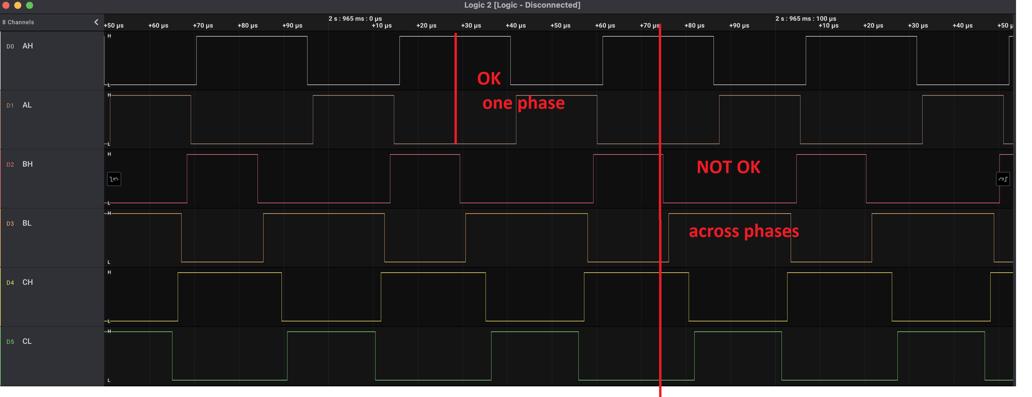
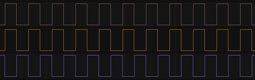
Attached are our waveforms generated by each pin to the MOSFET, labeled AH (Phase A high) to CL (Phase C low).


Any help would be greatly appreciated! Thank you in advance!

1 Like

@Parth_Raut

Welcome to the forum. It’s great to see people using SimpleFOC.

I’ve got great memories of Ann Arbor and UoM. Good pizza, lots of beer and very cold weather, hehe. There are some really good kids and professors there. Hopefully you will get this working.

Let’s see if anyone else, more knowledgeable than me, could contribute and answer your questions

Meanwhile… Debugging these types of issues is exceedingly complex due to the combination of code, unknown board and motor. Depending on how much time you have, unless your competition is really tight on schedule, there is something I could suggest. Since you are probably very short on time, you need to perform a differential debugging. In other words, get a known driver board that works for sure, run your code on the Teensy with the good board, make it work on that motor, then compare the signals and behavior. Unless you make your code work on a known good driver board, your task grows exponentially complex.

Even better, run this on a known classic Arduino board and check the signals, too. Teensy is a bit off the beaten path.

If you are really, really short on time, I could overnight to Ann Arbor a good driver board that is guaranteed to work open loop on your motor for you to perform a differential analysis. Not sure if that’s considered cheating however, so be very careful what you say and do here, as even though this is a public hobby forum, some of us have PhDs and MSc in that field. Please check the rules and bylaws of your competition. Academic honesty is something I take very seriously.

Let me look at the waveforms you sent, I may be able to see something obvious.

Cheers,
Valentine

Edit1: The Altium schematics is very hard to debug because you replaced all components with aliases. Unless there is a BOM, it’s not very useful.

Edit2: It’s not clear from your description, are the PWM signals the MCU control pins or the MOSFET inputs from the drivers? In other words, where are the test points on the schematics?

Edit3: The PWM do not look complementary, centered PWMs. There is some problem with the timers, but it’s really hard to tell since it’s not clear what are the test points. Could be the drivers are getting messed up due to non-centered timers and inserting dead time where the signals incorrectly overlap. That’s just a wild hypothetical guess, without knowing the low level details.

1 Like

Hi Valentine @Valentine ,

Thank you so much for your help! Your answer to someone else’s post help us figure out what was wrong, and we were finally able to get open loop working!

Here is a video: File from iOS.MOV - Google Drive

The solution was to reduce the motor.voltage_limit and motor.velocity_limit, our values were too high.

You do bring up great points. The PWM signals are the MCU control pins, straight from the teensy. We used a logic analyzer to probe those pins easily.

We want to make sure our PWM is correct. I have attached a clearer picture of the PWM below.

Do these not look like correct center-aligned PWM with deadtime insertion? What would be a good way to tell?

Thank you,
Parth

@Parth_Raut

Great. At least you got it spinning.

Phase to phase they are centered, however, interphase they are not. Probably not a big deal as the voltage gets smoothed out by the inductance in the coils. Usually if they are generated by the same timer, they should be perfectly centered, but no big deal. As long as the motor runs smoothly you will be OK.

Correct, you probably saturated the PWM and it was just giving you all 0 or 1 for portions of the sine wave. As I said, Teensy may have some issues.

Good luck with the competition and please post some more videos and pictures of your experimental setup. There are many people here that would like to learn from your experience and know what the competition is about.

Cheers,
Valentine

Check this post it may help you.

https://community.simplefoc.com/t/gimbal-motor-overheating/1034/6

@Valentine

Thanks for all the help, we really appreciate it!

Yes of course, we hope to be more involved in this forum, as we found simpleFOC invaluable to our progress towards competing next month. We are the Supermileage team, you can find us here: https://umsm.engin.umich.edu/

Feel free to visit us in Ann Arbor, we would love to have a mentor!

Thanks,
Parth

Hey @Parth_Raut,

Yeah, for your high torque application and for better current sensing if you wanna implement one in the future, I agree 100% with Valentine, you’ll need to sync the timers for all three phases.

However, i am not 100% sure that that is your issue. We do for some architectures have the unsynched timers for different phases. Particularly for software 6pwm for stm32 devices. And this does not necessarily produce this behaviour.

I am looking in your code and you have a really high target velocity and a very high voltage limit. I’d suggest you to use the commander and set the two values separately using the serial port. And start with the voltage limit of 1-2V and the target velocity of 1-5rads. And build up slowly to 30+rads.

Too high voltage limit will create huge currents going through the motor which might produce the behavior you’re getting. Too high velocity target would make the motor unable to follow and could make the motor Skipp which could produce similar behavior.

[Edit] sorry now that I read your other posts I see you’ve found the solution. :slight_smile:

1 Like

They may be even better off using a high end Nucleo instead of Teensy. as much as I like Teensy, the Nucleo boards are far superior in terms of documentation, and support, and the high end STM chips are similar in performance.

@Parth_Raut please consider using a good high end nucleo board instead of the Teensy. Also in the future if you want to develop a fully integrated board, STM MCUs are perhaps your best choice.

https://www.mouser.com/ProductDetail/STMicroelectronics/NUCLEO-H755ZI-Q?qs=%252B6g0mu59x7KOiBeEHDTYVQ%3D%3D

https://www.st.com/en/evaluation-tools/stm32-nucleo-boards.html#products

Cheers,
Valentine

P.S. I’m not in any ways affiliated with ST Microelectronics, this is just an off-handed advise.

1 Like

Hi @Antun_Skuric thanks for the response! That was exactly what fixed our problem.

@Valentine thanks for the recommendation! We are definitely going to switch to STM Nucleo for our next competition. We’ve tried to align the PWM as best as we can, setting the counter value, but they are still off by a few nanoseconds. Here is a picture:

We hope to use a better board where we can get all the pins on the same counter, but thats currently not possible with the teensy. We’re stuck with teensy for our upcoming one since its in less than a month.

Thanks for all the help, really appreciate it!

Parth