SimpleFOC stepstick

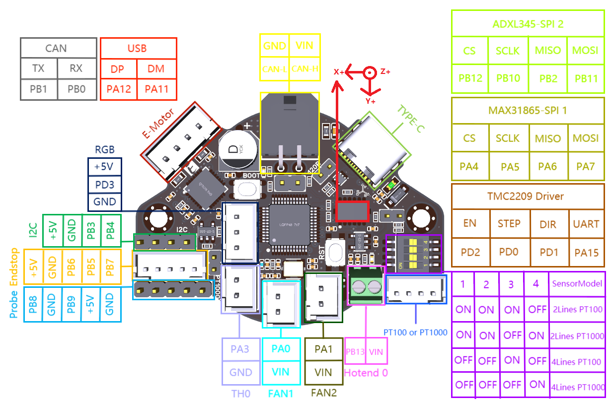
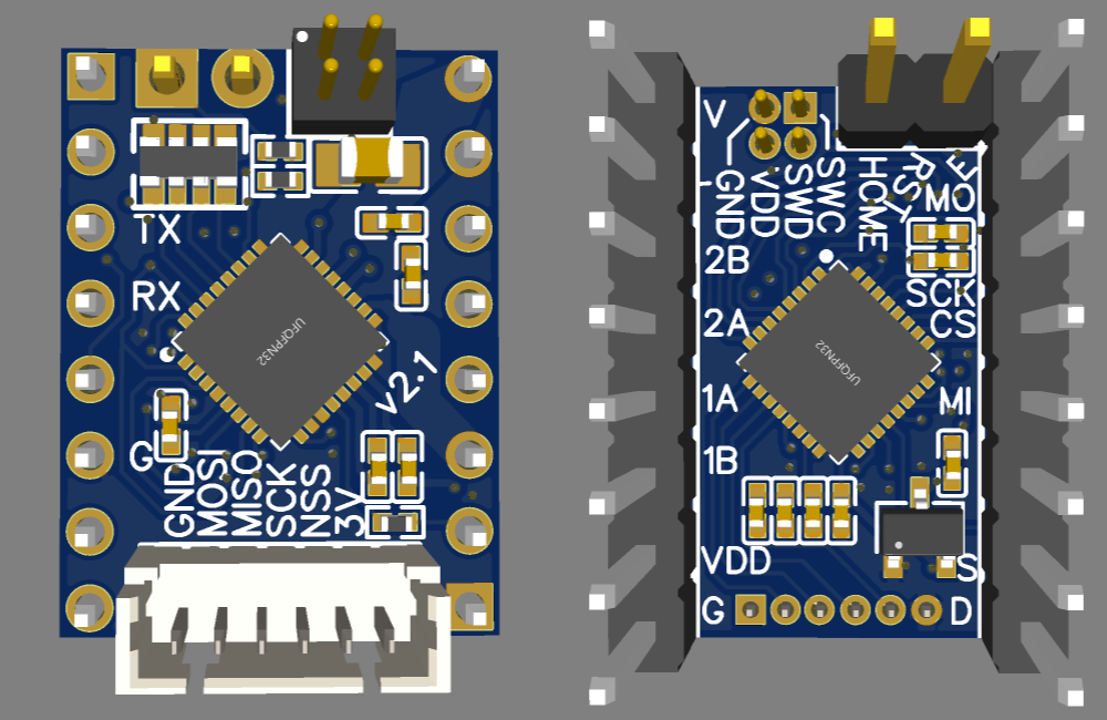
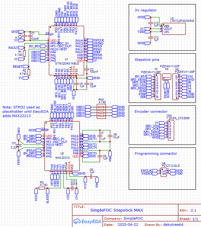
Thanks, I will use that SPI pinout too then.

I agree with your master plan. Step/dir is for plug-and-play with firmware that expects open loop steppers (Marlin, Klipper, GRBL, etc.). The stepstick will be running closed-loop for better torque and ability to recover from momentary overload, but the motherboard will treat it like any open loop driver.

The “full SPI” mode should simplify the motherboard firmware since it won’t need to do the real-time conversion of planner curves to step/dir pulses, but it will still need to do the planning to ensure that all axes are coordinated to reach target positions and velocities at the same time while keeping within acceleration limits. I’m not very knowledgeable on real-time motion systems, but it seems like you could use the existing trapezoidal planner code on the motherboard even if the drivers are generating S-curves internally. For each motion g-code, send a packet to each driver over SPI containing the end position and 3 trapezoid phases: acceleration (duration, end velocity), cruise (duration), deceleration (duration, end velocity). If all drivers generate S-curves for the acceleration/deceleration phases, they should remain coordinated since the duration of each phase is the same on all axes.

I haven’t even tested them standalone yet, much less in a 3D printer, so no lessons learned yet regarding the viability of relying on PID loops to respond quickly enough to keep up with open loop steppers. I’m sure it would be fine if you use all SimpleFOC stepsticks, but I’d like to offer the BLDC spiral extruder as an upgrade for existing printers without having to convert the entire motion system to closed-loop.

I am in the still pretty far from being able to make a functional PnP. So far I have been able to write a new camera backend/pipeline in Golang, Vision pipelining in Golang (using OpenCV bindings) and an almost functional UI. I have switched focus on the motion side of things and have been spending time to figure out the best motion system. I started with klipper and figuring out how to integrate it with openPNP. But soon found that to be subpar. In my quest, I seem to be ending up in one rabbit hole after another. But it has been a rewarding journey so far.

I’ve also tried to promote simpleFOC in the Duet3d/reprap forum.
They are known to be more open-minded than the guys behind Klipper.
@amken3D
Their controllers usually have onboard drivers or external drivers, but there is also a STM-branch which works on BTT and Mellow/Fly boards (stepstick and SPI conform)
These RRF compatible boards don’t require an Raspberry, which is another Plus, IMHO.

The issue with closed loop stepper motor on an normal 3d printer is that is adding more wires for control. In open loop ,driver is installed on printer mother board it is controlled by step/dir interface while 4 wire (energizing 2 coils) going to the stepper motor. If you add closed loop on an stepper motor you need to add minim 4 (5V,GND A,B) to maximum 6 (5V,GND,CS,MOSI MISO,SCK) more wires depending on the encoder type installed on the stepper motor.
On klipper they solved this issue installing the tool-board directly on the stepper motor back. The tool - board has its its own microcontroller and stepper driver and mosfets drivers for extruder heater, fans with corresponding connectors also connector for thermistor, Z-probe, limits probes, additionally with accelerometer to help reduce vibrations . It could be easy to add an encoder on the same board.
The tool-board communicates with. klipper via serial (usually 250000 bauds) or CANBUS and can use 4 wire(24V, GND,TX,RX)
I attached a picture for tool-board from BIGTREETECH also the one from Bambulab A1.


Hi @midelic_m, Yes, I am quite familiar with Klipper and common hardware use cases. Take a look at https://amken3d.com/ I have designed and am manufacturing boards and tool head boards just like the example BTT board :slight_smile:

Something like this is really nice: GitHub - atopile/spin-servo-drive: SPIN ✨ - Servos are awesome 🤩. Spin is an open-source hardware project to make it easy and cost effective to use fully-fledged BLDC servo motors 🚀

But of course there’s different ways to approach the problem, as evidenced by all the cool suggestions made so far.

Love this thread.

1 Like

About servos, years back I modified an RC servo removed the potentiometer and added an 5040 magnetic encoder for closed loop. For control I used an DRV8838 with Atmega328 microcontroller with step/dir signals provided by the printer mother board. The servo was used as direct drive extruder for my 3d printer at that time. The most tricky part was to modify the potentiometer with attaching radial magnet and board. See some photos.

That’s also a cool hack, but in this case the word “servo” doesn’t mean cheap DC motors like RC-servos but rather it’s referring to any position controlled motion solution, like the systems high end 3D printers use.
In the spin servo drive the motors are NEMA17 BLDCs.

For X ,Y and Z axis you can use an high end servo as the weight is not a factor. But for direct drive extruder head you need it as light as possible. The RC brushed servo was just and example for an direct drive extruder. There are cheap brushless servos that may be used with the same principle with encoder and different driver, I’m not aware of light ~ 50grams high end “closed” loop servos. There are light BLDC 2805 -2805 motors that can be used, I’m working on one now to adapt a simple foc integrated driver.

No, you are right nor am I :slight_smile:

So you have to build them yourself with SimpleFOC like @o_lampe ‘s extruder design :slight_smile:

I’m aware of @o_lampe and and VDE100 extruder struggles. I’m modeling something like this below. I will use AMT-103V encoder.


I’m waiting for my custom driver board to come from China. Valentine Mosquito board is expensive at this stage.

[OT]
I never liked to grind the flanges of the bearings in a VDE100 design.
I might have found a better option:

I saw that on duet forum. It is a good find. But before that .I want to ask you something. Did you test VDE 100 with " classic" ground bearings and BLDC-Simplefoc driver? I know you tested with classic extruder configuration (Bondtech clone) but that is different you have a gear ratio, it may need less force to push the filament.
I’m interested on a VDE100 with BLDC test before starting optimization .
I know in open loop the BLDC motor is overheating. I suspect that may be overheating also in closed loop with VDE100.

I don’t want to hijack this thread too much, so let’s keep the answer short and maybe use the Duet-forum instead.
I never tested a screw extruder with a BLDC motor, because I use magnetic encoders. But others feared the filament might soften, while it passes the hollow shaft. I can’t copy that with my latest NEMA08 “pacemaker” design.
A screw extruder motor needs less torque, but higher revs compared to my Bondtech extruder. ( ~2000 steps/mm versus 700 steps/mm with the bondtech gears)

Long time no update! I still haven’t gotten around to testing the DRV8955 boards, and I probably never will. Apparently I didn’t read the STM32 datasheet properly back then and left out a lot of capacitors it needs, so it may not run right.

I’ve been working on the MAX22213 version for the past couple days, and realized that I also failed at my goal of supporting both BLDC and stepper motors, because steppers need complementary PWM. But I think I’ve come up with a solution for it. PA11 can be TIM1_CH4 or TIM1_CH1N, and BLDC only needs 3 non-complementary channels, so if I use PA8 TIM1_CH1, PA10 TIM1_CH3, PF0 TIM1_CH3N, then PA11 can either give the complement to PA8 or a third regular channel.

Stepper:
2B/OUT1: PF0 TIM1_CH3N
2A/OUT2: PA10 TIM1_CH3
1A/OUT4: PA8 TIM1_CH1
1B/OUT3: PA11 TIM1_CH1N

BLDC:
2B/OUT1: NC
2A/OUT2: PA10 TIM1_CH3 (phase A)
1A/OUT4: PA8 TIM1_CH1 (phase B)
1B/OUT3: PA11 TIM1_CH4 (phase C)

Note: My driver is on the top side, so the stepstick pins are flipped vertically from the first image.


For stepstick pins, I’m using the SPI layout suggested by @amken3d (how’s your project going, by the way?), plus an extra 2 pin header up top to get a sensorless homing pin matching the DIAG pin on most TMC driver boards. Unfortunately this results in one dud pin between it and EN, which is VREF on the TMC boards.

Also troublesome is that it ate up the programming connector’s place, so I’ll either have to replace it with a 1.27mm pitch 2x2 pin header for SWDIO, SWCLK, 3V and GND, or just two 2.54mm pins sticking up for SWDIO and SWCLK and leave it to the user to figure out how to power it and get a ground wire to the ST-Link.

There’s also no good way to access UART for Arduino serial monitor. Two of the SPI pins will do it when not plugged into a motherboard, but if you’re trying to tune the PID on your 3D printer’s motors, it needs to be doable in-place. One option is to solder those pins pointing up instead of down into the motherboard. Obviously you wouldn’t be able to use SPI from the motherboard then, but if you could, then you wouldn’t need UART.

The encoder connector is the same as before. It’s a different SPI interface from the stepstick pins, so they can operate independently. And its pins are ADC inputs, so I can use my beloved linear hall sensors.

One dilemma is how to deal with some motherboards supplying 3.3V and others 5V to the VDD stepstick pin. My tentative solution is to use a 3V regulator, so 3.3V is enough extra to regulate down, and the output is still enough for most encoders.

Here’s the current state of things with still a ways to go. Routing is a struggle. Everything is spiraling around in a way that suggests I should rotate the MCU by 90 degrees, but if I do, there’s not enough room to squeeze all the lines past the LDO to get to the sense resistor vias.

Victory is mine!

I noticed the 4-in-1 resistor in Amken’s board and decided to give it a try. It turned out to be very helpful, as it allowed placing the sense vias between the resistor pads, leaving more space below for other lines to get through.

I did rotate the MCU 90 degrees, and moved the voltage regulator to the bottom left to make space for routing up top. It almost felt too easy after that. Only the upper left area is really congested. The top layer has a large empty area toward the bottom. And I even achieved my stretch goals of including a reset pullup resistor and dynamic control of the HFS pin (which changes the current sense range for better accuracy at low current).

I decided to go with the 1.27mm 2x2 pin header for programming, with the voltage supply pin connected to VDD so it goes through the regulator to eliminate the risk of connecting a 3.3V ST-Link pin to the 3V regulator output and frying it.

Unless anyone has any better ideas, I’m sticking with soldering two stepstick pins pointing up for UART. All MCU pins are utilized, so there’s no chance of breaking out an independent UART interface. And the encoder SPI pins don’t have UART. And the stepstick SPI pins don’t have ADC, which I want on the encoder connector for linear halls.

There wasn’t a good place for a reset touchpad, but that dud pin was nearby so I connected it up. Since motherboards are expecting to read a voltage from that pin, they shouldn’t bother it. I could fit a touchpad on the bottom side, but it would be inaccessible when installed in a motherboard. Or a tiny one next to the pullup resistor on top. It would be really crowded in there, but since the nearest thing is the ground pad of a sense resistor, and ground is what you want to touch to the reset pin to activate it, it wouldn’t be a problem to bump into it.