Unfortunately I’ve discovered that the current sense output on MAX22213 is unidirectional. Should I cut my losses and abandon the project, or make it work as best I can?
Stepper motors can be made to work fine with 4-channel current sense, though it will require custom ADC configuration since SimpleFOC only does up to 3 channels.
But BLDC can never do proper FOC since half the time only one channel gives usable output. If I assume there’s no phase lag, I could estimate the other two from the known voltage angle. But the discontinuity at the transition between each zone would likely be bad. So I’m probably restricted to using DC current mode, and estimating that while in single-sensor territory.
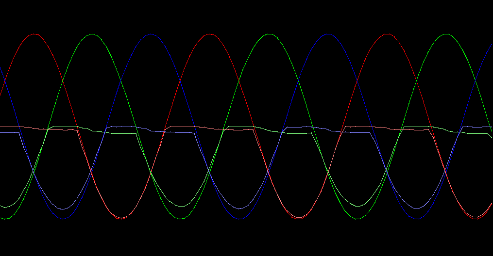
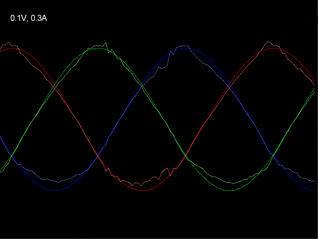
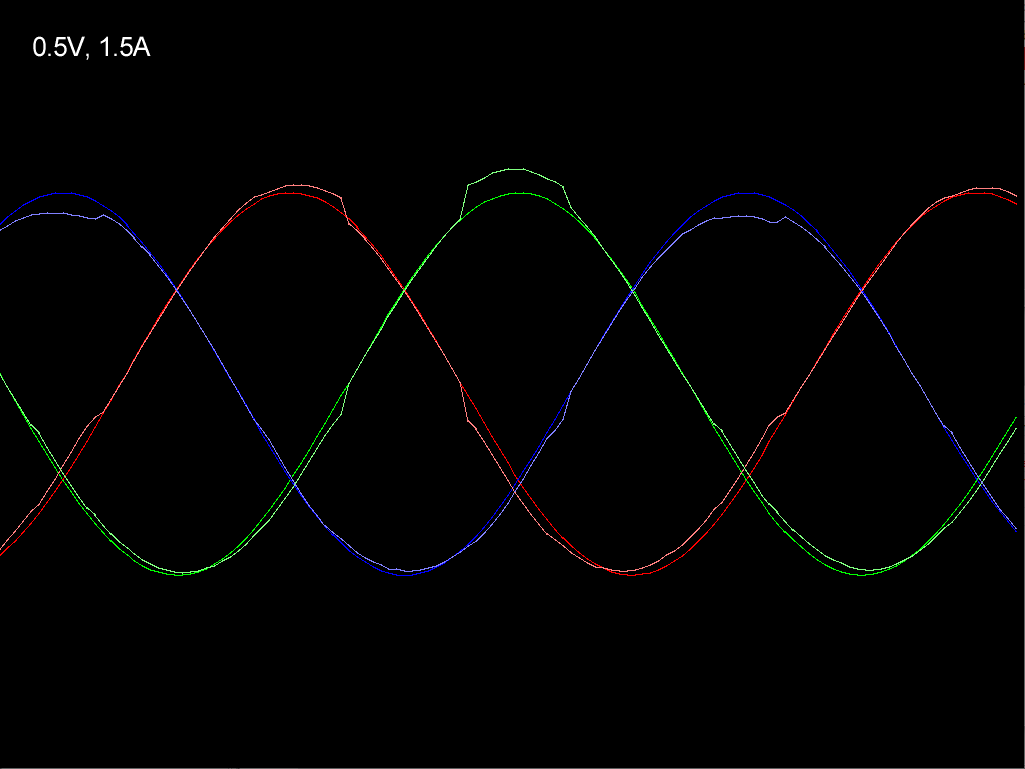
Here’s what the current readings look like compared to the output voltages (open loop velocity, so perfect sine waves). Their amplitudes vary by quite a lot. They match the sine waves more accurately if I give them a bit of upward offset too, but I’m not sure how to go about calibrating for that.
UPDATE:
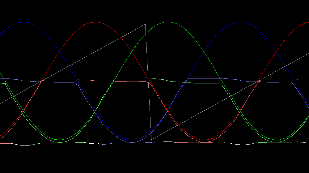
It looks like DC current mode will work, at least at low speed. The basic procedure is to divide the current by a sine wave to normalize it, and select whichever phase is closest to its negative peak. Then to reduce discontinuity at the transition from one phase to the next, I interpolate between two phases’ readings in the ±15° around the transition point (white segments in the DC current line at the bottom). The gray zigzag is electrical angle.
Here is the code:
  // The electrical revolution is divided up into 12 sectors of 30 degrees each.
  // When motor.electrical_angle is 0, phase A voltage is 0 and headed toward negative.
  // At motor.electrical_angle = 30 degrees, phases C and A have equal magnitude.
  // Sector 0 starts at motor.electrical_angle = 15 degrees and ends at 45 degrees,
  // and as the angle progresses through that range, the output fades from C's reading to A's reading.
  // The next 3 sectors use A alone, then fade from A to B, and so on.
  // sector -> phases used
  // 0   -> C,A
  // 1-3 -> A
  // 4   -> A,B
  // 5-7 -> B
  // 8   -> B,C
  // 9-11-> C
  // Normalize the current for each phase, so they have constant value rather than sinusoidal variation
  PhaseCurrent_s c = currentSense.getPhaseCurrents();
  float phaseCurrent[3] = {0,0,0};
  for (int i = 0; i < 3; i++) {
    float electricalAngle = _normalizeAngle(motor.electrical_angle - i*_2PI/3);
    if (electricalAngle > _2PI*14/360 && electricalAngle < _2PI*166/360) // Reading is valid from 0 to 180 degrees, but onlt 15 to 165 is actually used
      phaseCurrent[i] = ((float*)&c.a)[i] / _sin(electricalAngle);
  }

  // Select the phase with the highest magnitude for the electrical angle, and interpolate if near the boundary between two phases
  float electricalAngle = _normalizeAngle(motor.electrical_angle - (_PI/12) * _sign(motor.current_sp)); // Offset by 15 degrees so 0 corresponds to sector 11-0 boundary
  int intAngle = electricalAngle * (65536.0f*3.0f/_2PI); // Range is now 0-65536 for 120 degrees, 0-196607 total
  int sector = intAngle >> 14; // Range 0-11 (30 degrees per sector)
  int phase = sector >> 2;
  float estimatedCurrent = phaseCurrent[phase];
  if ((sector & 3) == 0) {
    if(--phase < 0) phase = 2;
    float c0 = phaseCurrent[phase], c1 = estimatedCurrent;
    float blend = (float)(intAngle & 0x3fff) / 16384.0f; // Interpolate between the two as the angle progresses through the sector
    estimatedCurrent = c0 + (c1 - c0) * blend;
  }
I hardcoded some gain and offset calibration to make the currents match closer to the voltage sine waves. Without that, the DC line steps up and down with the phase magnitudes, and the interpolation areas are slightly higher magnitude than they should be. Calibrating the gain would be no problem, but I don’t know how to sort out the offset from it. I may just go with a hardcoded 50mA offset, but I’ll need to assemble more of them and test to see how much variation there is.
For high speed, I have two potential approaches, both of which rely on detecting the peak of the sine wave, where the normalized current is equal to the raw measurement.
- Phase lag equal to the difference between the electrical angle where the measured current peak happened and the electrical angle where the voltage peak would be in open loop mode
- Each time a peak is detected, plug the current value into the equation here to estimate the phase lag.
I’ll try #1 first, since it’s more direct, and doesn’t require knowing the inductance. Either way, the phase lag will only be updated 3 times per electrical revolution. But since it’s only needed when the motor is spinning fairly fast, it will probably be fine.
UPDATE2:
I’ve gone about it all wrong. During the phase transition areas where two currents are good, the third phase is also known via the zero-sum rule so the DC current can be calculated exactly. Plus I can calculate the phase lag correction to use until the next two-phase window so the DC estimation from a single phase should be very accurate at any speed.