Request for Design Feedback: STM32G4 + DRV8316 BLDC Controller PCB
Greetings everyone,
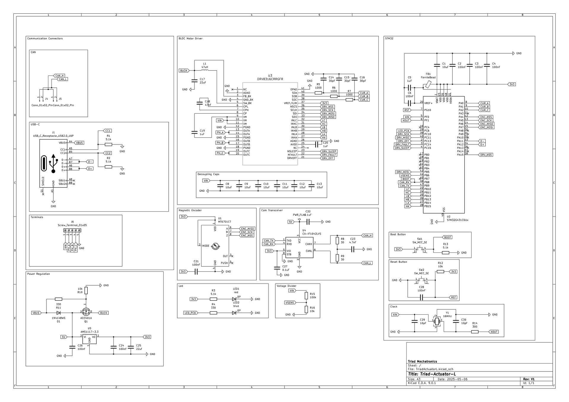
I’m seeking design feedback on a BLDC controller PCB I’m working on, based on the STM32G4 and DRV8316. This is my first hardware project—my background is in software—so I’d really appreciate input from more experienced members of the community.
This design draws heavily from several excellent projects shared on this forum, including:
The kicad file, STM Cube file, Reference Documents, and Block Diagram are on the project’s GitHub.
I haven’t yet started the PCB layout, as I want to ensure the schematic is correct before proceeding. I do have a few technical questions I hope the community can help with:
Questions
SPI Interface Conflict
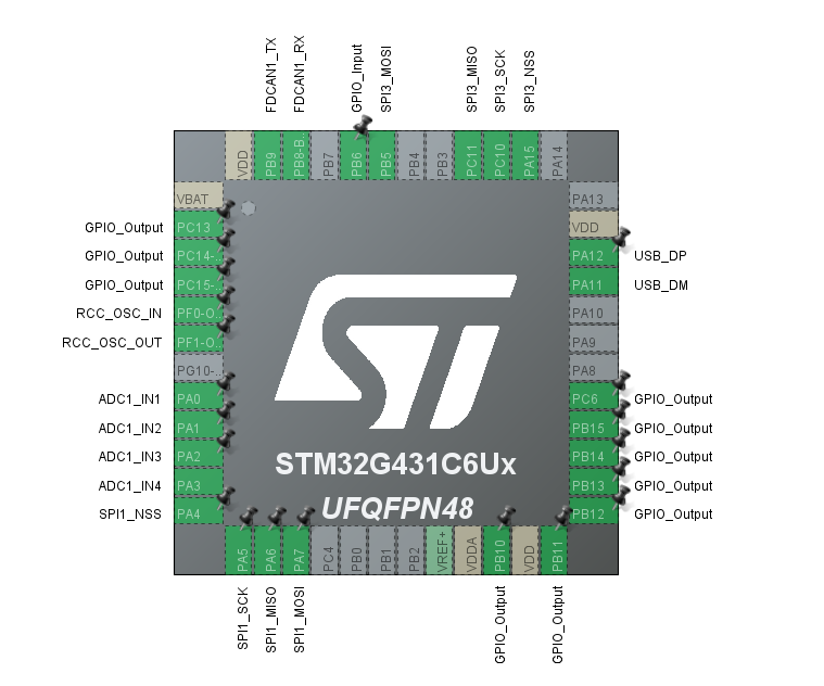
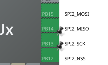
The STM32G431C6 provides three SPI interfaces. Two are used—for the encoder and the DRV8316. I’d like to use the third SPI for an external encoder (as seen on the ODrive Micro), but this one shares PF0 and PF1, which are also used for the external crystal.
Is it possible to use this SPI interface and an external crystal?
Alternatively, is it viable to omit the external crystal and rely on the internal oscillator while still maintaining full functionality?
Adding I2C via Qwiic Connector
I’d like to include a Qwiic connector for I2C communication, but I’ve noticed most BLDC controller designs favor CAN due to its robustness in noisy, high-EMF environments.
Would adding I2C be useful, or is it likely unnecessary or unreliable in this context?
Flashing via USB-C vs ST-Link
I haven’t exposed the ST-Link debug/programming pins, as I was under the impression the controller could be flashed directly over USB-C.
Is this assumption correct, or will I need ST-Link access to flash the firmware (especially during early development)?
Any comments, corrections, or suggestions would be greatly appreciated. Thank you all in advance!
Pressing RST while holding the BOOT button will put the MCU in upload mode. Code can then be uploaded from Arduino IDE.
Using ST-link or USB during development is your choice, but it is a good practice to expose SWDIO and SWCLK pins.
Notes and Suggestions:
The DRV8316 is low current driver. It is not suitable for driving A2212 motor with high loads. Microspora was tested on A2212 motor with light loads and slow speeds.
If this is your first PCB, I would suggest to make the board at a comfortable size and not too compact. Exposing test pins can be helpful for troubleshooting
I wish you good luck on this project. Since you’re from Software background, the firmware part shouldn’t be an issue for you.
My case was the opposite, It took me two days just to get the motor running. Without the guidance from Runger, it would have been impossible.
Can you share more info about your project and use case
Ok, great point. I will be exposing the appropriate ST-Link pins using a Tag connector so I don’t have to add another component I might not use.
I am working on a robotic actuator controlled via the CAN interface. The A2212 motor will be coupled with an 8:1 planetary gearbox for torque multiplication. I plan to power the motor using a 2- or 3-cell LiPo battery.
To evaluate power requirements, I conducted power draw tests using a benchtop power supply and a drone ESC. The results were as follows:
Voltage
No Load
Light Load
High Load (Near Stall)
6V
0.52 A
1.5 A
2.5 A
9V
0.65 A
2.5 A
3.5 A
12V
0.71 A
3.0 A
8.0 A
Based on this testing, I believe the DRV8316 motor driver can handle the expected current. However, unlike drone applications where the motor is actively cooled by airflow, in my use case it will be enclosed in a 3D-printed housing. Therefore, I will avoid running the motor at full throttle for extended periods to mitigate heat buildup.