I’ve recently done another iteration of the mini board, and I’ve decided to go for the DRV8316 chip this time.
As it already has low-side current sensing and a bit better current capacity than DRV8313 or LAN9252 its a great candidate for a minimal starter-kit type of boards.
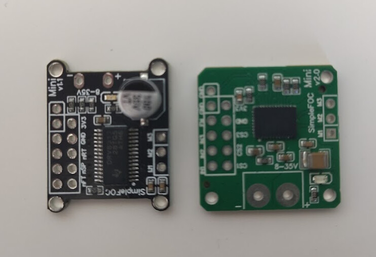
I’ve done a few iterations and the results are pretty good. Here is the comparison to the mini v1.1
This board is a bit more forgiving than DRV8313 based mini v1.1 or SimpleFOCShield v3. It does allow running a bit more powerful motors and allows for easier starting with SimpleFOC.
The main idea behind the board is twofold:
A simple and minimal board to start with SimpleFOC
A template board that you can be realtively easily remixed for your own projects
IMPORTANT NOTE
This board uses 3x PWM for motor control and can be used with any MCU arcitecture supported by SimpleFOC. However, not all microcontroller architectures do have the support for low-side current sensing. Find more info in the docs. Typically Arduino UNO does not have it.
So if you want to use this board for the current based torque control make sure to choose the MCU architecture that does support it.
At this stage the board is still very experimental and I might go ahead and add inline current sensing to it as well.
Let me know what do you think.
I have not worked that much with power electronics for the past 25 years. So now I looked at the datasheet of this DRV8316, and I am just amazed by how much power and functions such a single integrated circuit can handle.
For my future sewing machine project I looked at the b_G431_esc, and it got significant limitations regarding other posible interconnections to other controls and indicators. Using this DRV8316 with posibly the Bluepill MCU provides much more posibity for other interfaces at a low-price level.
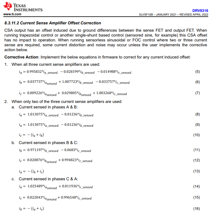
I noticed that the low side current sense is bidirectional, and I think this is important.
When looking at the B current signal, you have about 7 % “crosstalk” from the C current, when B and C are sensed. Will a normal MCU have sufficient calculation power to make such corrections at high sample rates of the current?
Just another drop in the bucket for anything with an FPU, but Bluepill does not. STM32G4 and ESP32 are better.
Implementation wise, we have a class for configuring the SPI version of DRV8316 in the drivers repository. Perhaps we should add a current sense class in that file as well, which inherits LowsideCurrentSense and performs the correction in getPhaseCurrents?
@Antun_Skuric I would probably not add inline sense. Keep the cost low and design as simple as possible. The current PCB is beautiful how little you had to use the bottom layer I think this will be a very popular item in the shop.
My only suggestion is to move the I/O holes to the left so you can fit the fourth mounting hole in the upper right. Technically 3 holes is enough, but having 4 on the board gives more options which 3 to use.
Yeah, we do have quite a few MCU families that do support it and even if they do not, you can still use it as any other mini.
You’re right. I’ve aligned all the holes to be able stackable on a breadboard so I cannot really move it much. Maybe it is just easier to make it a 1mm longer and make it 24x25mm and that way everything should fit.
This is a good question. I’m not sure what would be the best approach, probably the an addition to the drivers repo. @runger might have some more experienced suggestion
Another feature that might be necessary with DRV8316 is the driver’s dead time compensation. In my tests I’ve found that I needed to add a 0.1V of dead-time compensation to make the currents completely sinusoidal.
The torque control will work without it too, but the currents are not as nice.
I have to ask questions about this, because I got only little knowledge of the differences of these MCUs. It might be a bit off topic, but it is about a good MCU to be used with this Mini driver.
FPU - is it short for floating point processor? So you mean that the Bluepill don’t have that?
According to this link: https://docs.simplefoc.com/stm32_mcu
I notice that the Bluepill uses the STM32F103C8 processor with Cortex-M3. I assume it is in the STM32F1 family, and according to same link it got current sensing support from simpleFOC. In the manual for the STM32F103, it says that it got one-clock-cycle multiplication, but I guess, that it is not the same as FPU.
What makes the STM32G4 family a better choice than the STM32F103 ?
I know the Arduino IDE. Do they support some of the STM32G4 MCUs?
Can you suggest a PCB with a STM32G4 MCU?
Ah, I hadn’t thought of that. It looks like you can move the motor and power holes to the right until they meet the next grid line. The mounting holes are already not quite aligned, and the pins will serve as mounting on breadboard so I think it’s ok.
This is with power holes at x=-820mil, connector holes starting at -720mil, motor holes at -420mil. The voltage silkscreen got squashed up against that capacitor, but still somewhat readable, and it can be put on the back as well. The 1210 capacitor may need to be moved a bit.
Correct. It has fast integer math, but floating point is emulated so takes many cycles to perform each operation. I haven’t measured exactly how much, but according to an4044 the FPU is over 10x faster. SimpleFOC is written with all floating point math, so the newer MCUs are worth using since the cost is not much higher.
I’ve only used the bare chip G431 (and B-G431B-ESC1, but as you said earlier it is very limited on I/O), so I can’t recommend any particular breakout board. The official Nucleo boards are a little pricey. I don’t see many options on aliexpress, but this one with STM32G431CBU6 for $6 looks good https://www.aliexpress.us/item/3256806892940504.html
It should be able to drive 2 SimpleFOC Minis easily. 3 or 4 will get a bit slow, but still usable if you don’t need to spin more than a few thousand RPM (G431 is around 15-16KHz update rate for a single motor with current sense).
Now, I found out to open the documentation on the design. I think, that the aim is to keep production costs low. Some of the suggestions I now provide do increase costs, so it will be all right to make the evaluation that this will not be reasonable. I do know a bit about EMC, so some comments will be about that.
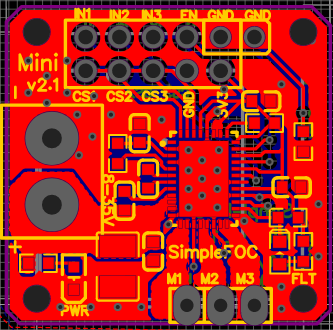
I like to see that most of area on the PCB on both sides is utilized as a ground planes.
I would suggest, that you move one of the ground connectors in the outer row to the left, and move all the other connectors one step to the right. This will cause a better return path for the external signal wires.
The PCB tracks for CS1, CS2, CS3 might be moved a bit to the left, so they are better covered by the buttomlayer ground plane to make a return path.
Some resistor buck-converter solution is utilized. Consider to be able to deliver power to a MPU board like @dekutree64 suggested.
Thank you very much for your answer. From my experiments with a demanding speed control on a BDC motor, I like to have 10 kHz update rate on current control and 2 kHz on speed control. Therefore I like to see that the possible update rate here is above that.
I don’t think I said anything about that, but I did think about it With the current configuration, the 3v3 pin can output 30mA. STM32G431 will need to be underclocked to run on that. Table 21 on page 76 of the datasheet says 170MHz is 25-29mA typical, and is basically proportional to clock rate. From table 34 I would estimate another 10mA used by peripherals, giving 35-39mA total, plus some for LEDs. So underclocking to 70% would probably be safe enough.
A 47uH inductor greatly increases DRV8316’s buck current, but the internal regulator is still limited to 30mA so it wouldn’t help unless we want to replace the 3v3 pin with 5V unregulated buck output, or add it as a new pin. Most MCU breakout boards have an onboard 3v3 regulator that can take 5V input, so it is worth considering.
Yeah, that sounds good. motor.loopFOC is the current control update, and motor.move is motion control, so you can update them at different rates. There’s even a built-in way to do it using the variable motor.motion_downsample.
The 15-16KHz number is when running both every time, so reducing the motion control rate could maybe get two motors up to your desired rates. However I just remembered that the lowside current sense code only supports one motor, and I don’t know how feasible it would be to change that.
Yes, I guess it would start to get messy with two independent motors. I think you like to have two ADCs for each motor with current control, so you can sample two currents at the same time. But a fast ADC may get the two values close in time. Perhaps it will be possible to make current control on two motors with one MPU having four or more ADCs, but it still becomes messy.
I noticed R5, 1k resistor from motor power supply to the LED1 to gnd. I think it is to signal power on. I think the possible power loss may be above the specifications for the resistor. The loss at 24 V will be about 0.5 W and at 35 V about 1 W. It will be hard to cope with full power supply range from 5 to 35 V this way. Perhaps it is better to use one of the low voltage supplies for this LED. I guess that 2 mA will be sufficient for some LEDs.
I think it will be nice to have a voltage divider on Vcc, with an output, so you can measure Vcc by the MCU. But it is no must. Normally power supplies used for power have got a current limit, and when you exceed the limit, the voltage collapse. When your software monitor this voltage, you can avoid this collapse at high power accelerations of a motor. You may be able to avoid this collapse by other means, and you can also make a voltage divider by external hardware. I just found this possibility nice in my applications.
I noticed, that the Arduino platform do support a ESP32-S3 processor, but I do not see STM32 processors to be supported there. I tried to look up about the ESP32-S3, and it do have two ADCs and a FPU. But this MPU seems more optimized for wireless communication. I noticed, that the RP2040 processor only got one ADC.
I was able to put it in and be able to select PCBs with STM32 MCUs in the Arduino IDE. My only recent experience is with the old Nano Atmega 328P MPU. One of the hardest parts for me was to get to the point, where I had a program with a LED flashing. From there it got easier.
But last time I ordered some electronics from China, I got a PCB with a STM32G030C8T6 MPU, just because they sold them cheap, and I was curious. I newer tried it yet, but now with your help, I got a way forward to try it. And if I get a LED flashing, I shall try to buy the STM32G431 board you suggested. But I think further help about this will be off topic in this thread.
I mean, this chip is 7 years newer than the DRV8313 used in SimpleFOC Shield v3. The integrated current sensing is a major reduction in PCB complexity. I would certainly buy at least one board.
I had a look at the circuit. I see it’s very small so I’d need to get a solder mask or pay for assembly which makes most sense in larger numbers of purchasing whereas I just need one.
I have a comment which is perhaps the gain pin could be configurable to its different settings with solder bridges? You would just need to populate a 0R resistor (replace with 1M for the high impedance gain setting) and have 1 other “DNP” unpopulated resistor (for pull up with 0R or 47K to AVDD for the other 2 gain settings).
For my application I have ~24V power with 20R between windings so max ~2.5A → gain of 1.2 is perfect.
It would also be good to have spaces for an RC filter on SOA/SOB/SOC. We had those noise issues with the ACS712 - I know the DRV8316C uses shunt resistors but still.