DRV8316 + STM32G431 design request for comments

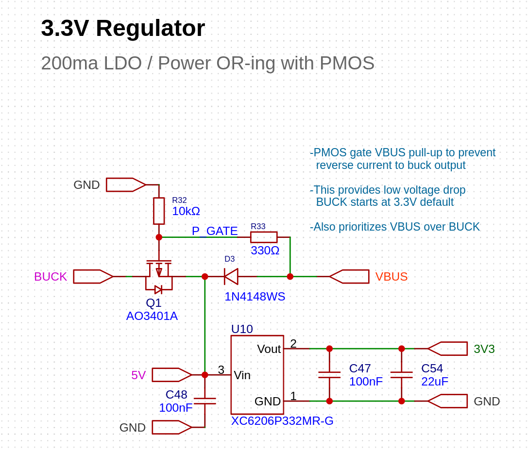
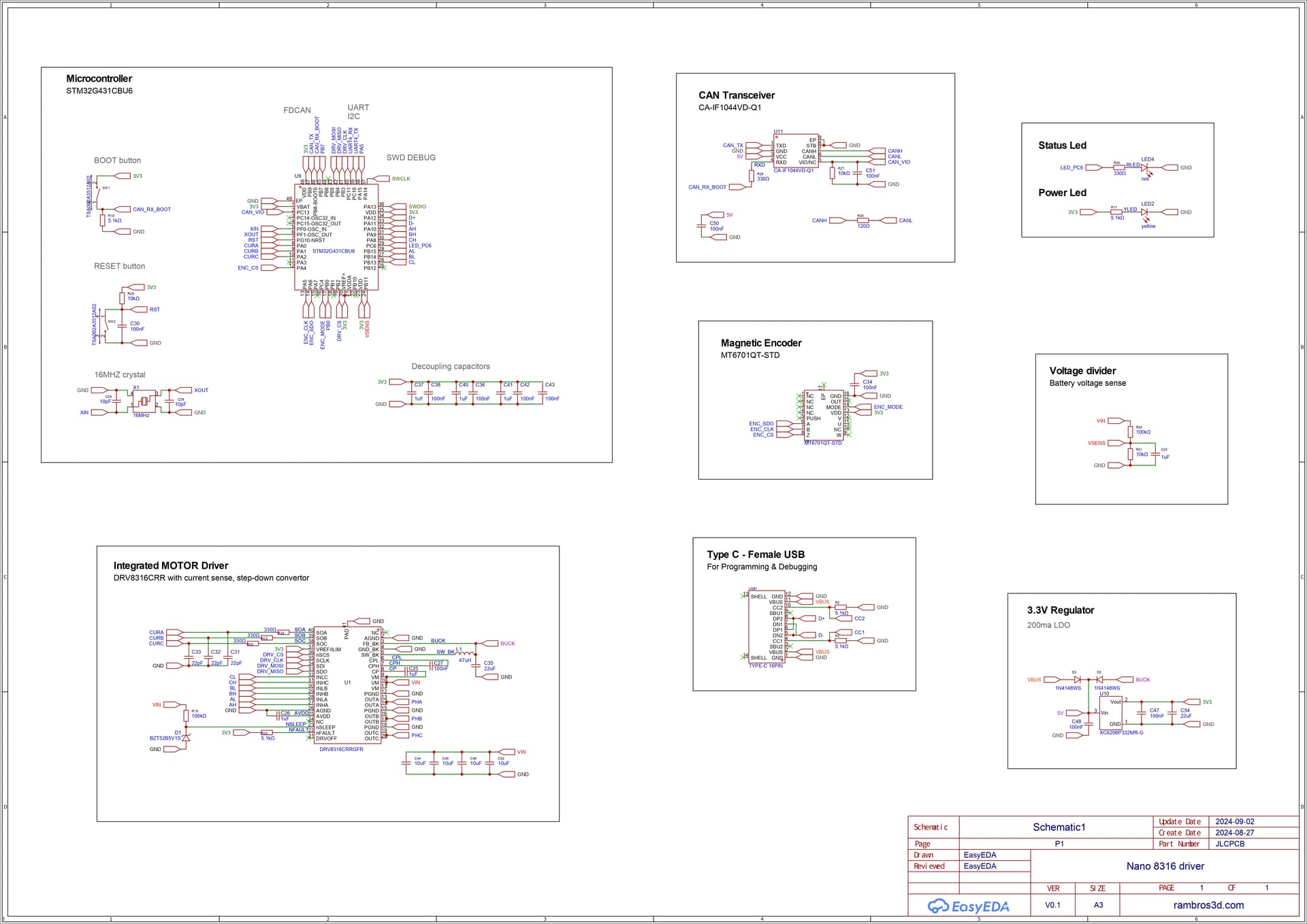
Here’s the schematic:

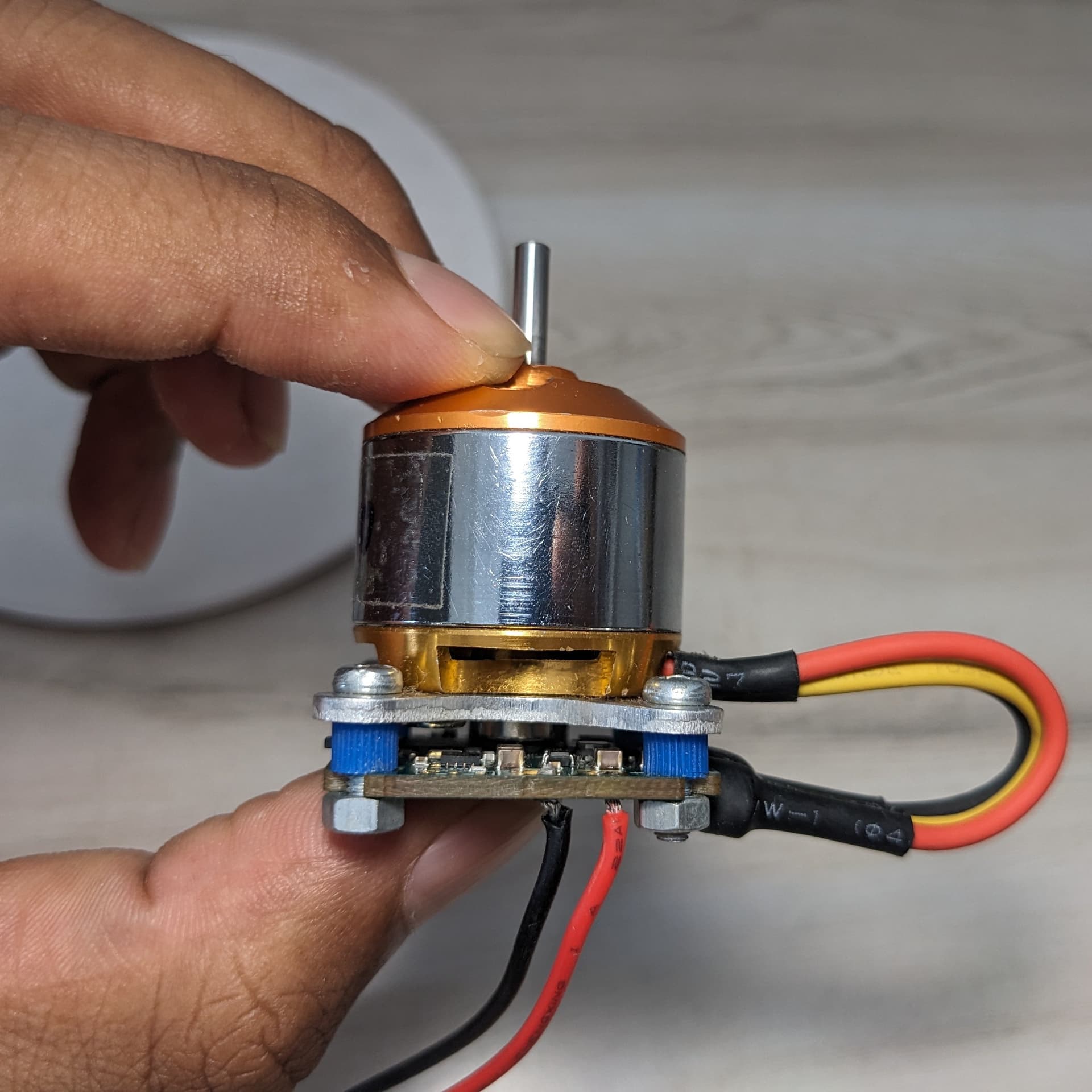
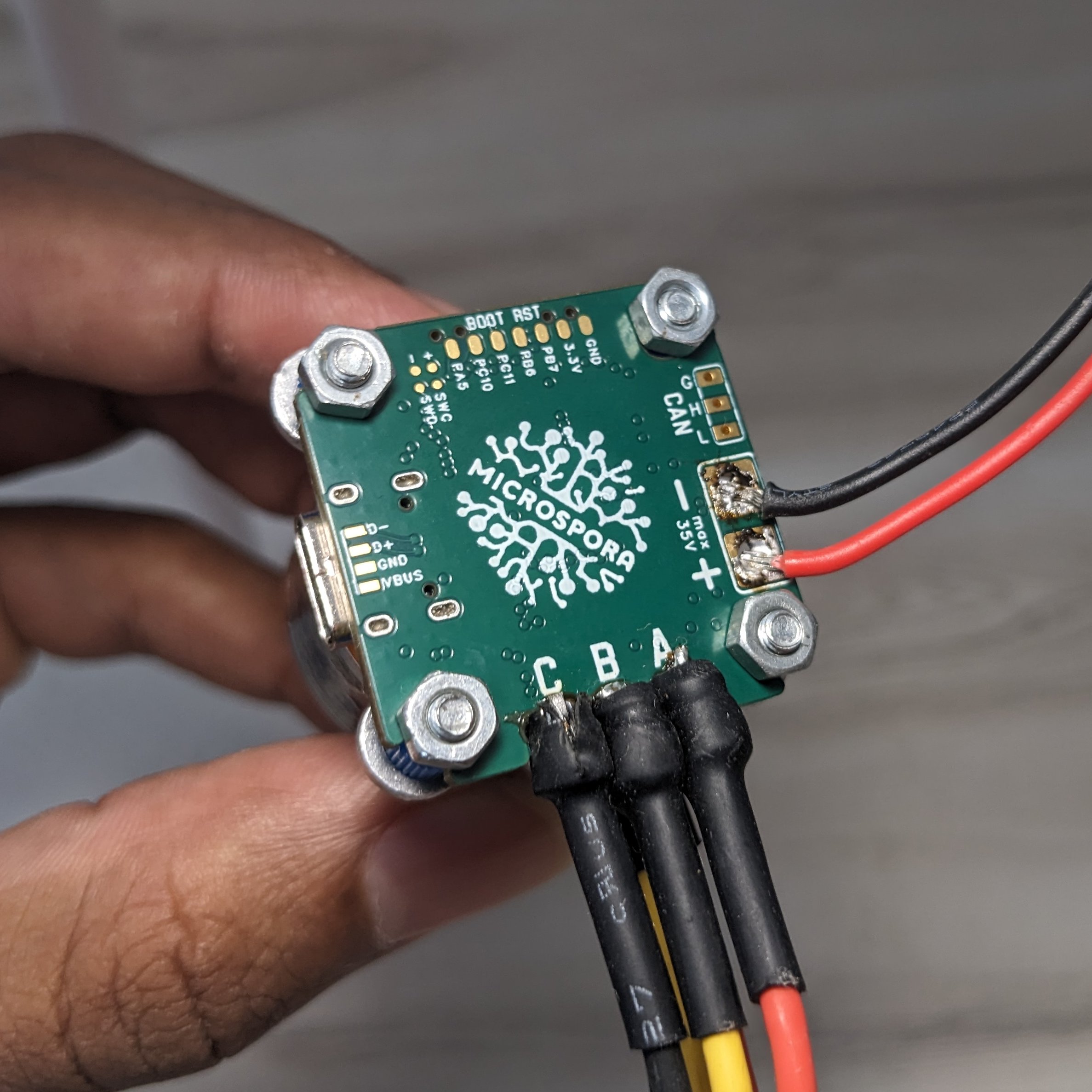
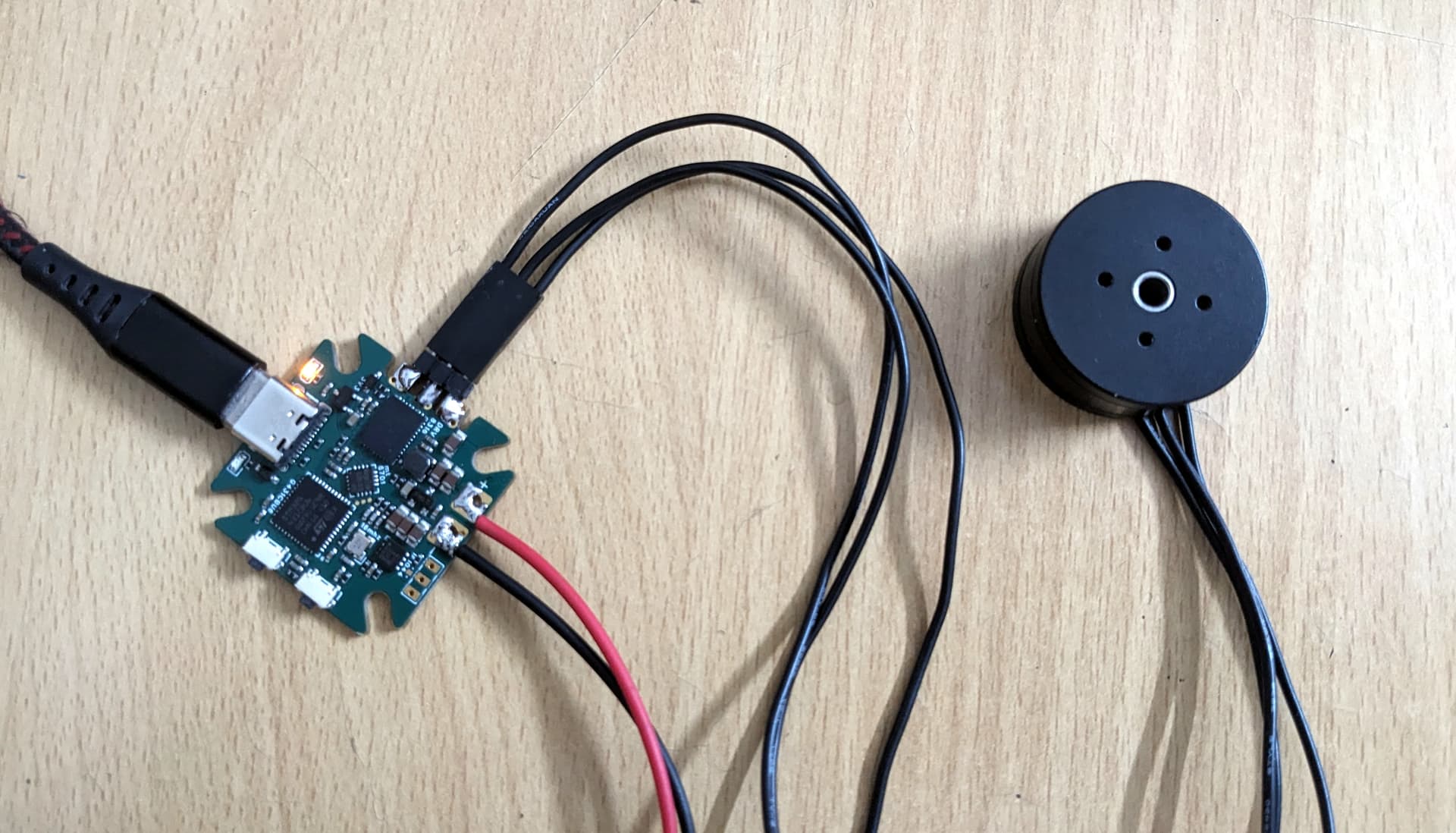
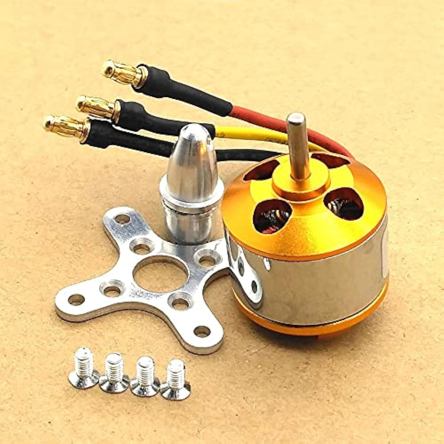
The board will be used to control this A2212 motor. We use these type of motors in our 3D printed RC vehicles. (trucks, cars, excavators…)

Interfaces:

  • CANBUS
  • UART
  • I2C
  • PWM
    I will mostly use PWM for now. The rest are just for testing purpose.

Notes:

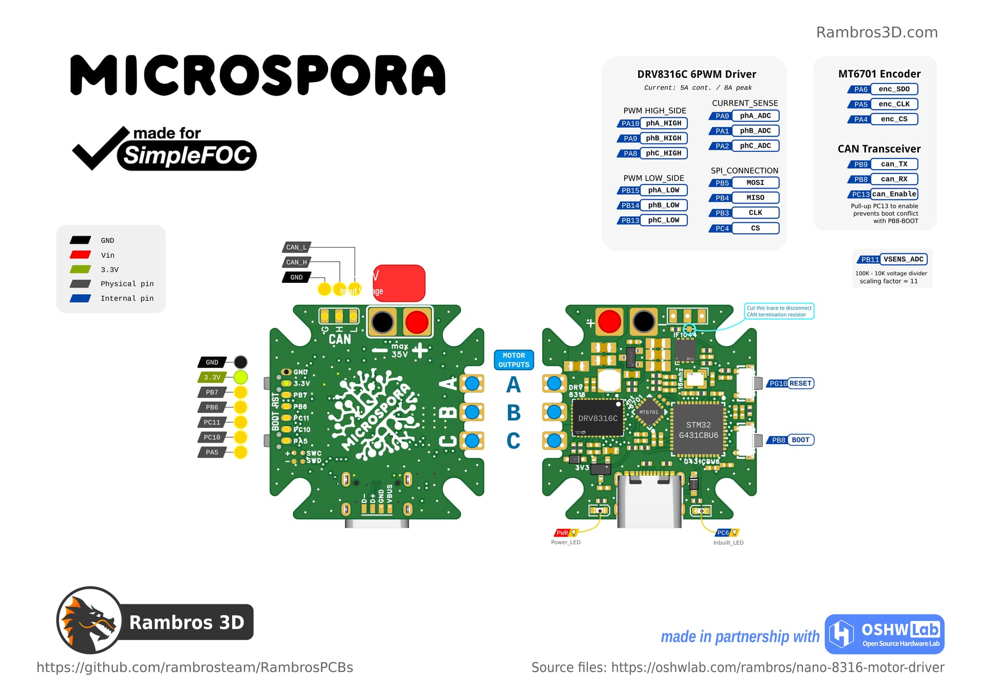
  • DRV8316 motor driver wired with 6PWM. Used a 5V zener as vref to provide pullup for NSLEEP
  • VIO of IF1044VD CAN transceiver connected to PC13 to hopefully prevent conflict of RXD pin with PB8-BOOT0
  • 10k pull-up for NRST, don’t want capacitative touch for reset
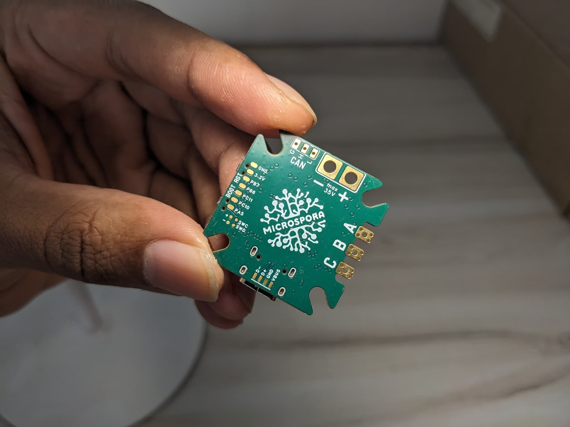
 :joy: @dekutree64
  • Planning to go with a 1.2mm 6-layer board and economic assembly

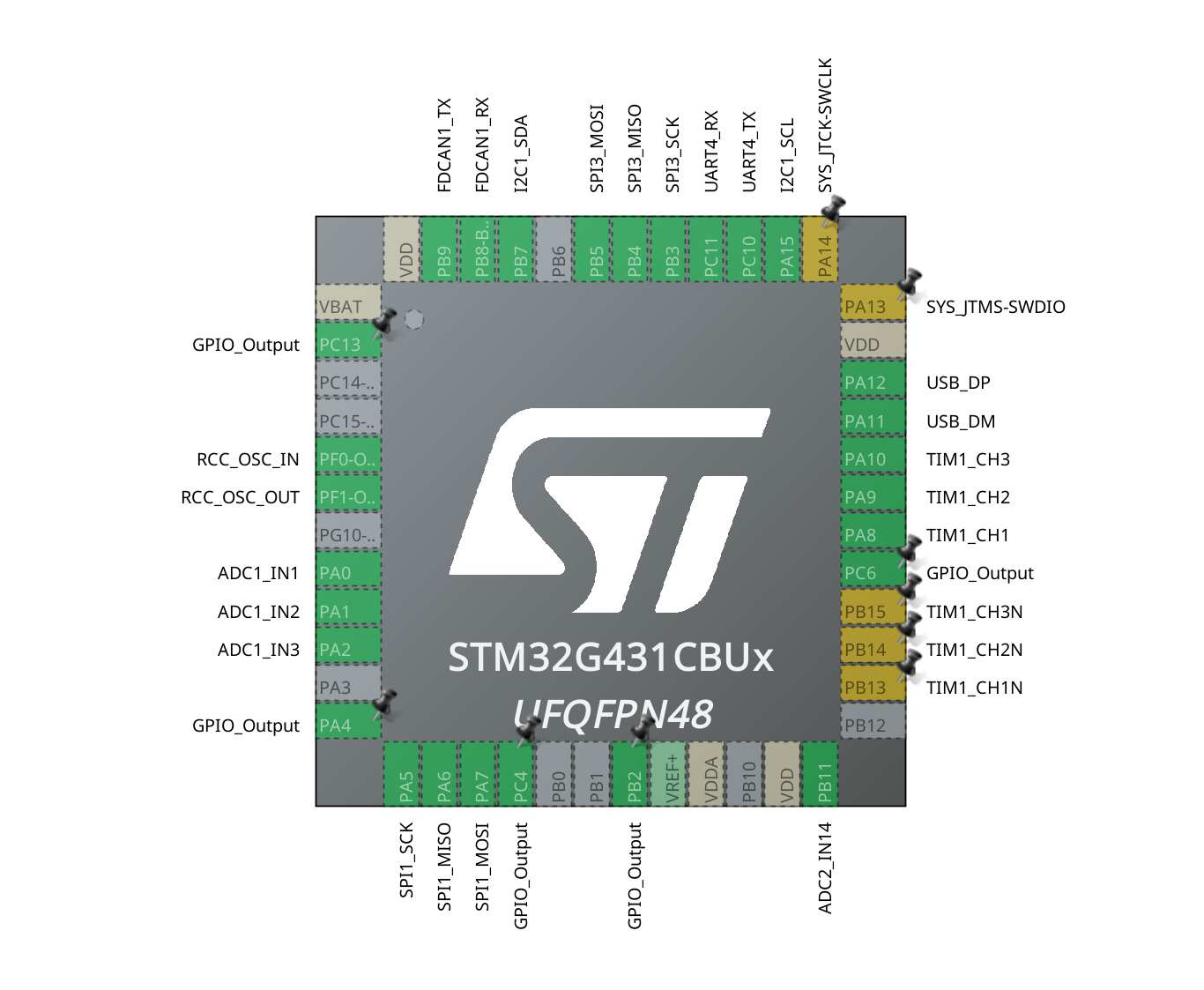
This will be my first PCB using a STM32 MCU. My previous PCBs were limited to ESP32 series and RP2040
I used the CubeMX to determine the pins - PWM, I2C, UART, FDCAN


I would like to program this directly from USB with Arduino IDE. Do I need to use STM32Cube IDE or ST-Link to configure this MCU for the first time? Or can we directly start using this board from the Arduino IDE.

Thank you everyone

Hey @rambros, I think it would be a better idea to make a separate forum post for your driver board schematic, that way it’s really clear which board people are commenting on.

1 Like

You’re right.
@runger thanks for taking care of this issue

Hey, I have split it off to its own topic, as per @nanoparticle’s request

Regarding your questions:

Not if you don’t need a special BOOT0 configuration. It has a built-in boot loader so it is good to go.

I don’t think so. You need to select a board definition in ArduinoIDE before you can use a board, and I am not sure the generic board definition for G431 will work:

  • you seem to have a different clock configuration to the generic variant, using an external oscillator
  • you probably want FDCAN and CORDIC support
  • you’re using USART4 and none of the others which will lead to strange serial port object naming

So working with this board will require a little bit of work on the part of the user. You can make it easier for them by providing a board definition, but they will still have to install that from wherever you provide it.

Taking a quick look at your schematic, here is my feedback:

  1. Would recommend adding a limiting resistor to your crystal oscillator, even if you just use a zero ohm resistor.
  2. Would recommend exposing the remaining IO as a pin header or connector, though maybe these are on a different page because I don’t see your SWD connector here either
  3. DRV8316 buck starts in 3.3V mode by default, and the diode forward voltage plus LDO dropout voltage might be too low for the mcu in this initial condition.

Other than that, looks pretty good!

You sure 8316 is big enough for that motor? That’s a tiny driver. You’ll be tripping like the finale on a Burning Man festival.

Cheers,
Valentine

PS Please read very carefully page 70, table 9-1, line #2 of the design document.

@Valentine you have a good point.

In our tests the peak consumption was only 6-7A and the average is 2-3A. It is borderline near the safety margin, I usually like to have atleast 2x.

Beyond 6A at 11.1V (3S), The 3D printed gears started melting. So the model is not compatible more than 60W. That’s why I stuck with DRV8316, since board size should also be small - I will have to rethink my choices.

Thank you, I totally missed that part. I was just looking through the board variants

I will have to make it compatible with the generic board def.
And enable FDCAN and CORDIC in code.

If I get rid of the crystal (to save some board space), the MCU will use the High Speed Internal clock. This might have enough accuracy for PWM and ADC. And make the Clock Recovery System work with the USB connection. Thanks again

Thank you - Thats something I never thought of. I will look into that :+1:

I usually add the connectors at last after the schematic is finalized.

You’re right I should fix this too
Thanks again

Users who want this will have to set appropriate build flags in the environment. Unfortunately you can’t enable them just with code if they are not in the board definition.

It will work fine with the internal oscillator, but it does affect performance if you’re into very high performance use cases…
Someone here in the forum compared the velocity stability of a turntable with and without external oscillator and there was a difference.

Thank you, I looked into the thread you were referring to.

And you have also convinced me to create a new board def - that looks like the best way forward.
I thought of using B_G431_ESC1 variant but it cant use USB DFU since the (PA11) D- is used by CAN_RX.

I will fix all the issues and concerns everyone mentioned. Thanks a ton guys :+1:

If you do decide to create a board definition, I can offer to host it here if you like: GitHub - simplefoc/simplefoc_arduino_boards: Arduino board vendor files for SimpleFOC boards - just send us a pull request :slight_smile:

Also, as an alternative, working with new boards is far easier in PlatformIO. For PlatformIO you could provide a GitHub project including all the needed files to get your board working with custom clock and all, which people could just git clone and use with a standard PlatformIO install.

1 Like

@runger That’s awesome, I will create a pull request when the board is tested.

@nanoparticle I have used a power ORing with PMOS to address the voltage drop issue you mentioned

Here’s the link to the full schematic:
https://pro.easyeda.com/editor#id=9ac00872234849bb980a836700ccab2e,tab=*c797a62a637c408481f37c2b62597a91

2 Likes