Read a potentiometer continuously? on STM32 and analogRead()

Hello,

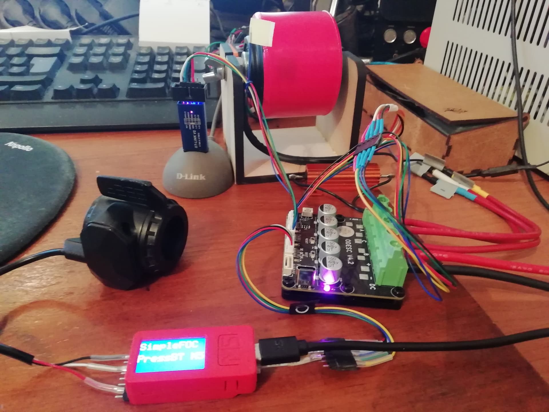
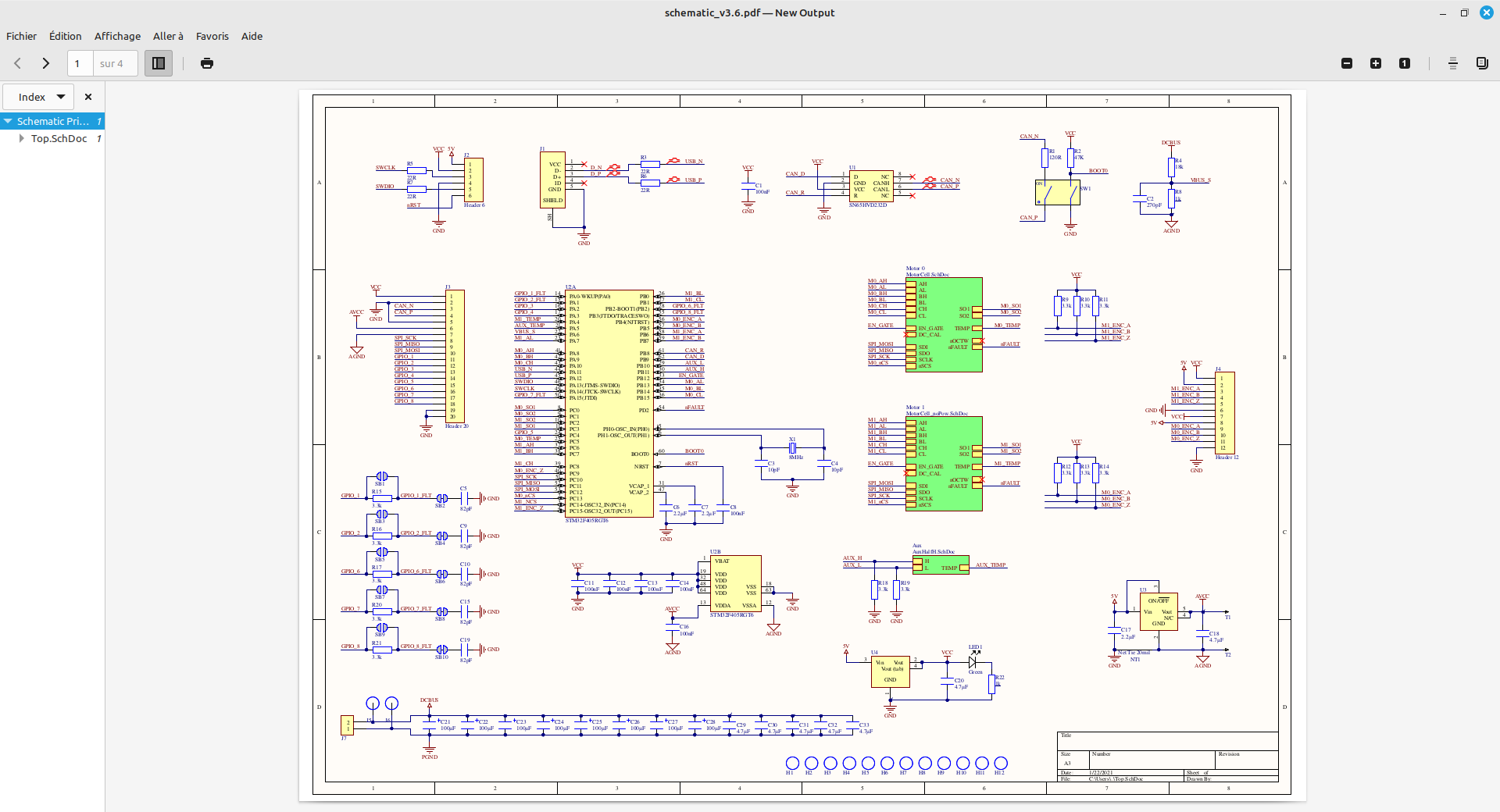
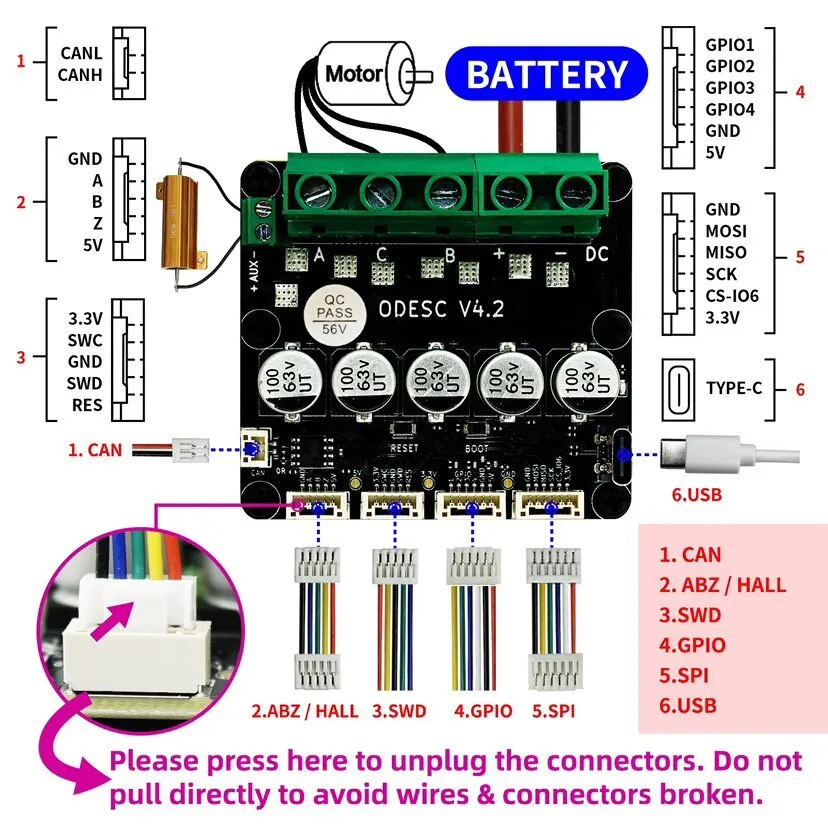
I bought an ODESC 4.2 card (24volt) with STM32F405RGT6, a Chinese card that runs under Odrive3.6.

https://fr.aliexpress.com/item/1005005725467528.html

I got it to work with SimpleFOC :slight_smile:
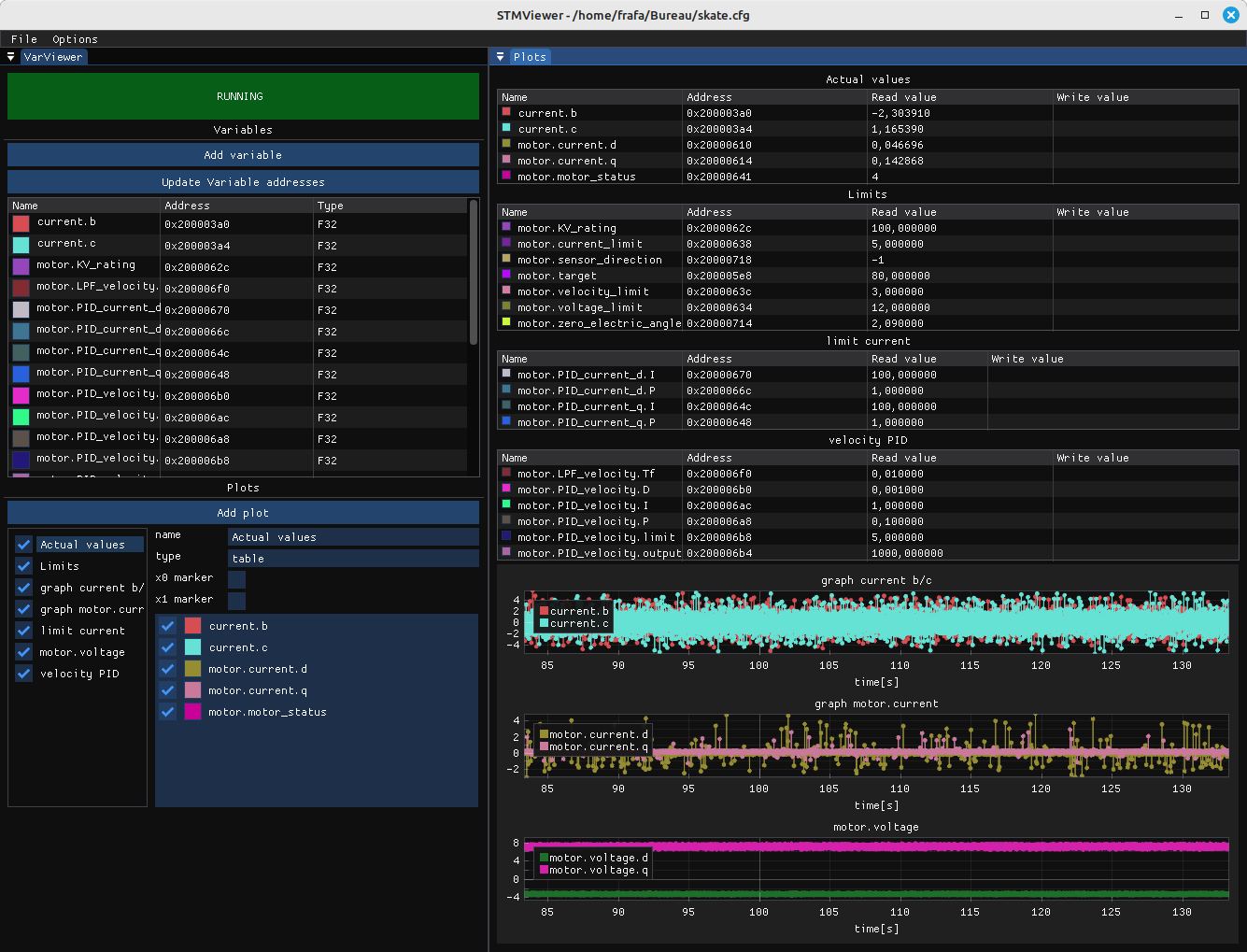
It works perfectly if I drive it with STMViewer and a “St-Link V2”.
The motor is a skateboard motor in 24v 150w and 10 poles with Hall effect sensor.

I can’t get a continuous potentiometer reading to work properly.

I first tried adding analogRead() from GPIO ==> PA0 to the loop,
It doesn’t work, it disturbs the motor operation,
analogRead() slows down the loop too much…

So I thought I’d add a connection with “SoftwareSerial.h” and “Commander command = Commander(mySerial)”.
and “Commander command = Commander(mySerial);”
Likewise, each time a potentiometer parameter is sent, makes the engine jerk…

How do you continuously read a potentiometer?
sorry, my English is very bad :frowning:

My code test build_opt.h:

-D HAL_OPAMP_MODULE_ENABLED
-D PIO_FRAMEWORK_ARDUINO_ENABLE_CDC
-D PIO_FRAMEWORK_ARDUINO_NANOLIB_FLOAT_PRINTF
-D PIO_FRAMEWORK_ARDUINO_USB_HIGHSPEED_FULLMODE
-D SIMPLEFOC_DISABLE_DEBUG
-g -ggdb

Arduino:

/*
  SimpleFOC_STM32F405RGT6
  odrive 3.6 - odesk 4.2
  Hall sensor example code

  This is a code intended to test the hall sensors connections and to demonstrate the hall sensor setup.

  odrive_example_encoder.ino
  https://github.com/simplefoc/Arduino-FOC/blob/dev/examples/hardware_specific_examples/Odrive_examples/odrive_example_encoder/odrive_example_encoder.ino

  https://community.simplefoc.com/t/problems-with-custom-firmware-for-odrive-v3-5-using-simplefoc/2743
  #include <Arduino.h>
  #include <Wire.h>
  https://github.com/simplefoc/Arduino-FOC/tree/master/examples/hardware_specific_examples/Odrive_examples

*/

#include <SimpleFOC.h>

//M0
#define A_HALL1 PB4
#define A_HALL2 PB5
#define A_HALL3 PC9

//M0
//#define M0_IA // _NC ????????????
#define M0_IB PC0
#define M0_IC PC1

// Odrive M0 motor pinout
#define M0_INH_A PA8
#define M0_INH_B PA9
#define M0_INH_C PA10
#define M0_INL_A PB13
#define M0_INL_B PB14
#define M0_INL_C PB15

// M1 & M2 common enable pin
#define EN_GATE PB12

//Pole pair
#define PP 10

//Temp
#define M0_TEMP PC5

// Motor instance
BLDCMotor motor = BLDCMotor(PP);
//BLDCDriver6PWM driver = BLDCDriver6PWM(PC6, PA7, PC7, PB0, PC8, PB1, PB12);
BLDCDriver6PWM driver = BLDCDriver6PWM(M0_INH_A, M0_INL_A, M0_INH_B, M0_INL_B, M0_INH_C, M0_INL_C, EN_GATE);

// low side current sensing define
// 0.0005 Ohm resistor
// gain of 10x
// current sensing on B and C phases, phase A not connected
LowsideCurrentSense currentSense = LowsideCurrentSense(0.0005f, 10.0f, _NC, M0_IB, M0_IC);

// Hall sensor instance
// HallSensor(int hallA, int hallB , int cpr, int index)
//  - hallA, hallB, hallC    - HallSensor A, B and C pins
//  - pp                     - pole pairs
HallSensor sensor = HallSensor(A_HALL1, A_HALL2, A_HALL3, PP); // PP = xx aimants / 2 = pole pair

// Interrupt routine intialisation
// channel A and B callbacks
void doA() {
  sensor.handleA();
}
void doB() {
  sensor.handleB();
}
void doC() {
  sensor.handleC();
}

//▬▬▬▬▬▬▬▬▬▬▬▬▬▬▬▬▬▬▬▬▬▬▬▬▬▬▬▬▬▬▬▬▬▬▬▬▬▬▬▬▬▬▬▬▬▬▬▬▬▬SoftwareSerial▬▬▬▬▬▬▬▬▬▬▬▬▬▬▬▬▬▬▬▬▬▬▬▬▬▬▬▬▬▬▬▬▬▬▬▬▬▬▬▬▬▬▬▬▬▬▬▬▬▬
#include <SoftwareSerial.h>
// SPI pinout mosi/miso ==> Utilisé pour serial RX/TX
#define SERIAL_RX PA3 //PC12
#define SERIAL_TX PA2 //PC11
// Set up a new SoftwareSerial object
SoftwareSerial mySerial =  SoftwareSerial(SERIAL_RX, SERIAL_TX);

// https://docs.simplefoc.com/communication
// instantiate the commander
Commander command = Commander(mySerial);

// motor SimpleFOCStudio ==> M
void doMotor(char* cmd) {
  //command.motor(&motor, cmd);
  command.target(&motor, cmd);
  //command.motion(&motor,cmd);
}


//▬▬▬▬▬▬▬▬▬▬▬▬▬▬▬▬▬▬▬▬▬▬▬▬▬▬▬▬▬▬▬▬▬▬▬▬▬▬▬▬▬▬▬▬▬▬▬▬▬▬setup▬▬▬▬▬▬▬▬▬▬▬▬▬▬▬▬▬▬▬▬▬▬▬▬▬▬▬▬▬▬▬▬▬▬▬▬▬▬▬▬▬▬▬▬▬▬▬▬▬▬
void setup() {
  //▬▬▬▬▬▬▬▬▬▬▬▬GPIO1/GPIO2/GPIO3/GPIO4▬▬▬▬▬▬▬▬▬▬▬▬
  /*
    pinMode(PA0, OUTPUT); // GPIO1
    digitalWrite(PA0, LOW); // HIGH/LOW

    pinMode(PA1, OUTPUT); // GPIO2
    digitalWrite(PA1, LOW); // HIGH/LOW

    pinMode(PA2, OUTPUT); // GPIO3
    digitalWrite(PA2, LOW); // HIGH/LOW

    pinMode(PA3, OUTPUT); // GPIO4
    digitalWrite(PA3, LOW); // HIGH/LOW
  */

  //▬▬▬▬▬▬▬▬▬▬▬▬Temp▬▬▬▬▬▬▬▬▬▬▬▬
  pinMode(M0_TEMP, INPUT); // M0_TEMP PC5

  //▬▬▬▬▬▬▬▬▬▬▬▬SoftwareSerial▬▬▬▬▬▬▬▬▬▬▬▬
  // Define pin modes for TX and RX
  pinMode(SERIAL_RX, INPUT_PULLUP); // sur GPIO PA3
  pinMode(SERIAL_TX, OUTPUT); // sur GPIO PA2
  mySerial.begin(115200); // 115200 Set the baud rate for the SoftwareSerial object
  _delay(1000);

  //▬▬▬▬▬▬▬▬▬▬▬▬driver▬▬▬▬▬▬▬▬▬▬▬▬
  // pwm frequency to be used [Hz]
  driver.pwm_frequency = 20000; // 20000 max SRM32
  driver.voltage_power_supply = 24.0f; // power supply voltage [V]
  driver.voltage_limit = 24.0f;  // Max DC voltage allowed - default voltage_power_supply
  driver.init();// driver init
  motor.linkDriver(&driver); // link the motor and the driver

  //▬▬▬▬▬▬▬▬▬▬▬▬Current▬▬▬▬▬▬▬▬▬▬▬▬
  // ici passe pas ?

  //▬▬▬▬▬▬▬▬▬▬▬▬sensor▬▬▬▬▬▬▬▬▬▬▬▬
  sensor.pullup = Pullup::USE_EXTERN; // check if you need internal pullups
  sensor.init(); // initialise encoder hardware
  sensor.enableInterrupts(doA, doB, doC); // hardware interrupt enable
  motor.linkSensor(&sensor);
  _delay(1000);

  //▬▬▬▬▬▬▬▬▬▬▬▬mode▬▬▬▬▬▬▬▬▬▬▬▬
  // set torque mode
  // https://docs.simplefoc.com/foc_current_torque_mode
  motor.torque_controller = TorqueControlType::foc_current; // foc_current || dc_current || voltage
  motor.controller = MotionControlType::velocity; // angle velocity torque  // Control loop type
  // choose FOC modulation
  // FOCModulationType::SinePWM; (default)
  // FOCModulationType::SpaceVectorPWM;
  // FOCModulationType::Trapezoid_120;
  // FOCModulationType::Trapezoid_150;
  motor.foc_modulation = FOCModulationType::SinePWM;  // pwm modulation settings
  motor.modulation_centered = 1; // 1

  //▬▬▬▬▬▬▬▬▬▬▬▬ALL_PID▬▬▬▬▬▬▬▬▬▬▬▬
  // velocity PID
  motor.PID_velocity.P = 0.1f; // 0.2
  motor.PID_velocity.I = 1.0f; // 2.0
  motor.PID_velocity.D = 0.001; // 0.001
  //motor.PID_velocity.output_ramp = 1000.0;
  //motor.PID_velocity.limit = 1.0;  // ? current_limit [Amps] // https://community.simplefoc.com/t/setting-current-limits-in-main-loop/1972
  motor.LPF_velocity.Tf = 0.01; //0.01  // Low pass filtering time constant

  // angle PID
  motor.P_angle.P = 30.0; // 14.0
  motor.P_angle.I = 0.0;
  motor.P_angle.D = 0.0;
  motor.P_angle.output_ramp = 10000.0; // 10000.0
  //motor.P_angle.limit = 50.0; // ? velocity_limit [rad/s]
  motor.LPF_angle.Tf = 0.001;  // Low pass filtering time constant

  // current q PID
  motor.PID_current_q.P = 1.0; // 3
  motor.PID_current_q.I = 100.0; // 300
  //motor.PID_current_q.D = 0.0;
  //motor.PID_current_q.output_ramp = 1000.0f;
  //motor.PID_current_q.limit = 3.0; // https://community.simplefoc.com/t/setting-current-limits-in-main-loop/1972
  //motor.LPF_current_q.Tf = 0.005;  // Low pass filtering time constant

  // current d PID
  motor.PID_current_d.P = 1.0; // 3
  motor.PID_current_d.I = 100.0; // 300
  //motor.PID_current_d.D = 0.0;
  //motor.PID_current_d.output_ramp = 1000.0f;
  //motor.PID_current_d.limit = 3.0; // https://community.simplefoc.com/t/setting-current-limits-in-main-loop/1972
  //motor.LPF_current_d.Tf = 0.005;  // Low pass filtering time constant

  //▬▬▬▬▬▬▬▬▬▬▬▬Limits▬▬▬▬▬▬▬▬▬▬▬▬
  motor.velocity_limit = 3.0f; // [rad/s] (120[rad/s] ==> ~1200[RPM])
  motor.voltage_limit = 0.5 * driver.voltage_limit; // [Volts] // Calcul ==> 5.57[Ohms]*1.0[Amps]=5,57[Volts] // [V] - if phase resistance not defined
  //motor.voltage_limit = 24.0f; // [Volts] // Calcul ==> 5.57[Ohms]*1.0[Amps]=5,57[Volts] // [V] - if phase resistance not defined
  motor.current_limit = 5.0f; // Current limit [Amps] - if phase resistance defined
  motor.phase_resistance = 0.5f; // [Ohms]  // motor phase resistance // I_max = V_dc/R
  motor.KV_rating = 100; // [rpm/Volt] - default not set // motor KV rating [rpm/V]
  // commenter les 2 ci-dessous pour avoir le test au demarrage
  motor.zero_electric_angle = 2.09f; // 4.19  // zero_electric_angle
  motor.sensor_direction = Direction::CCW; // Cw/CCW // direction

  //▬▬▬▬▬▬▬▬▬▬▬▬SimpleFOCDebug▬▬▬▬▬▬▬▬▬▬▬▬
  // https://docs.simplefoc.com/debugging
  //SimpleFOCDebug::enable(NULL);
  //SimpleFOCDebug::enable(&mySerial);

  //▬▬▬▬▬▬▬▬▬▬▬▬motion_downsample▬▬▬▬▬▬▬▬▬▬▬▬
  /*
    Pour de nombreuses applications de contrôle de mouvement, il est judicieux d'exécuter
    plusieurs boucles de contrĂ´le de couple pour chaque boucle de contrĂ´le de mouvement.
    Cela peut avoir un impact important sur la fluidité et peut fournir de meilleures performances à grande vitesse.
    C'est pourquoi cette bibliothèque permet une stratégie de sous-échantillonnage très simple pour la fonction move()
    qui est définie à l'aide du paramètre

    La stratégie de downsampling fonctionne de manière très simple, même si la fonction motor.move()
    est appelée dans chaque boucle arduino, elle ne sera exécutée qu'à chaque fois que motor.motion_downsample sera appelé.
    Ce paramètre est optionnel et peut être configuré en temps réel.
  */
  motor.motion_downsample = 0; // 0 https://docs.simplefoc.com/bldcmotor

  //▬▬▬▬▬▬▬▬▬▬▬▬init▬▬▬▬▬▬▬▬▬▬▬▬
  motor.init(); // initialise motor

  //▬▬▬▬▬▬▬▬▬▬▬▬linkCurrentSense▬▬▬▬▬▬▬▬▬▬▬▬
  // https://docs.simplefoc.com/inline_current_sense
  currentSense.linkDriver(&driver); // link the driver
  currentSense.init(); // init the current sense
  currentSense.skip_align = true;
  motor.linkCurrentSense(&currentSense);
  //▬▬▬▬▬▬▬▬▬▬▬▬initFOC▬▬▬▬▬▬▬▬▬▬▬▬
  motor.initFOC(); // init FOC

  //▬▬▬▬▬▬▬▬▬▬▬▬command▬▬▬▬▬▬▬▬▬▬▬▬
  // https://docs.simplefoc.com/commander_interface
  // add the motor to the commander interface
  command.decimal_places = 4; // default 3
  command.add('M', doMotor, "motor exemple ==> M10"); // The letter (here 'M') you will provide to the SimpleFOCStudio

  //▬▬▬▬▬▬▬▬▬▬▬▬target▬▬▬▬▬▬▬▬▬▬▬▬
  motor.target = 0;

  _delay(1000);
} // End setup
//▬▬▬▬▬▬▬▬▬▬▬▬▬▬▬▬▬▬▬▬▬▬▬▬▬▬▬▬▬▬▬▬▬▬▬▬▬▬▬▬▬▬▬▬▬▬▬▬▬▬End_setup▬▬▬▬▬▬▬▬▬▬▬▬▬▬▬▬▬▬▬▬▬▬▬▬▬▬▬▬▬▬▬▬▬▬▬▬▬▬▬▬▬▬▬▬▬▬▬▬▬▬


//▬▬▬▬▬▬▬▬▬▬▬▬▬▬▬▬▬▬▬▬▬▬▬▬▬▬▬▬▬▬▬▬▬▬▬▬▬▬▬▬▬▬▬▬▬▬▬▬▬▬loop▬▬▬▬▬▬▬▬▬▬▬▬▬▬▬▬▬▬▬▬▬▬▬▬▬▬▬▬▬▬▬▬▬▬▬▬▬▬▬▬▬▬▬▬▬▬▬▬▬▬

// current https://docs.simplefoc.com/inline_current_sense
PhaseCurrent_s current;// getPhaseCurrents

float actual_rpm;
long loop_count = 0;// loop down-sampling counter

void loop() {
  current = currentSense.getPhaseCurrents();
  float current_magnitude = currentSense.getDCCurrent(); // https://docs.simplefoc.com/inline_current_sense#example-code

  /*
    //▬▬▬▬▬▬▬▬▬▬▬▬▬▬▬mySerial_send▬▬▬▬▬▬▬▬▬▬▬▬▬▬▬
    // On envoie au M5StickC-plus la vitesse en RPM
    if (loop_count++ > 1000) { // control loop each ~xx ms
      //actual_rpm = (sensor.getVelocity() * 9.5492968) * -1;
      actual_rpm = sensor.getVelocity();
      //mySerial.println(actual_rpm);
      String toSEND = (String(actual_rpm) + "\n");
      //mySerial.write((char*)toSEND.c_str());
      loop_count = 0; // restart the counter
    }
  */

  motor.loopFOC(); // main FOC algorithm function
  motor.move();
  command.run();

} // End loop
//▬▬▬▬▬▬▬▬▬▬▬▬▬▬▬▬▬▬▬▬▬▬▬▬▬▬▬▬▬▬▬▬▬▬▬▬▬▬▬▬▬▬▬▬▬▬▬▬▬▬End_loop▬▬▬▬▬▬▬▬▬▬▬▬▬▬▬▬▬▬▬▬▬▬▬▬▬▬▬▬▬▬▬▬▬▬▬▬▬▬▬▬▬▬▬▬▬▬▬▬▬▬

1 Like

It could be related to how slow Arduino analogRead is: Am I understanding how to use Hall sensors correctly? - #4 by dekutree64

On B-G431B-ESC1 boards here (among others) the analog signals are read using an interrupt triggered from the timer running the PWM output to do a read on the ADC (for current sensing). You can add arbitrary other channels to the ADC conversion though. It takes a bit of tinkering in the low level code but it may work better for you as the read should be orders of magnitude faster and you can just store in some variable for when you need it later to serial or whatever. There is example code for this in the SimpleFOC repo.

It’s because of how analogread works.
I started this PR but it turned out to be more complicated then I thought.

Thanks to you,

I will try to look at the operation of the ADC of B-G431B-ESC1
…/libraries/Arduino-FOC-dev/src/current_sense/hardware_specific/stm32/b_g431
to try adding to
…/libraries/Arduino-FOC-dev/src/current_sense/hardware_specific/stm32/stm32f4

Sending parameters with SoftwareSerial.h is also disruptive,
in short, RX/TX is not usable for the moment with this card…

I would be surprised if ODrive (at least it was an original design before being cloned) did not use the hardware UART peripheral on STM32? Are you sure you can’t just use hardware serial? This will be much much faster.

I tried, but I couldn’t get the USB OTG hardware to work …

I’m not a good enough coder …

it works very well under odrive 3.6 …

Hello
A Merry Christmas to all.

I can’t make analogRead() work to read a potentiometer and set the speed with my configuration,
It disturbs the current measurement and makes my power supply safe …

I tried it with:
analogRead() (on loop)
with
commander
with
GenericSensor

Same thing, no way to read my potentiometer, as soon as I turn on the power, the current measurement doesn’t work anymore.
if I use an analogRead, do you have a solution?

That’s all I need, the card works perfectly, and for the moment I’m using serial software and M5StickC-Plus to control the speed,
but I’d rather use SimpleFOC…

What code are you adding to the code you listed above do the potentiometer read? i.e what is the smallest bit of code that breaks things?

If you only do a analog read in the setup() and not the loop() does the motor still work?

If motor doesn’t work then I’d try a different pin (maybe there is a timer conflict).
If it does work then I’d try one of the following:

  • change the code to call the ADC less often in the loop() (it may be too greedy/slow to be in the main loop).
  • try a lower analogReadResolution - e.g analogReadResolution(8). Reducing to 8 or 10bit might speed up the read.
  • or a more complicated route is to use ADC + DMA. Not something I’ve done myself

ADC reading works very well on B-G431B-ESC1
By ADC I don’t have the level to implement …

I tried on this board 6 pins GPIO1 GPIO2 GPIO3 GPIO4 MOSI MISO for analogRead(pin)

No matter where I put analogRead(), even if I reduce the reading time, it preturbs the motor,
and my power supply goes into safety mode at current limit …

I’ve just tried adding: analogReadResolution(8); with analogRead(), (not connected to motor.move)
no better …

void loop() {
  motor.loopFOC();

  long now = millis();
  if (now - 250 > timestamp) { // 250 ==> 4x per second
    valPOT=analogRead(PIN_POT1); // ==> PIN_POT1
    timestamp = now;
  }

  motor.move();
  command.run();
}

Something odd is going on. Your code snippet looks sensible. Where do you define PIN_POT1? What pinMode are you setting it to. Can you try to move the read to setup(). Can you try to measure the time taken to do the read? I can’t imagine it’ll be more than 50us so I wouldn’t have thought it would have such a profound effect on the current.

Does odesc have a smart gate driver IC that stops MOSFET shoot through? If not then I guess you are relying on simplefoc to do that. Trying to figure out why your power supply is going over current and not your gate driver IC stepping in and/or reporting over current fault.

The code below works very well, the motor runs at 1200 rpm with no problems,
I tried these pins ==> (PA0 PA1 PA2 PA3 ==> GPIO1/GPIO2/GPIO3/GPIO4) and (SPI_MOSI PC11; SPI_MISO PC12)
but as soon as I add an analogRead(pin) it doesn’t work anymore …(tested whithout and whith serial connexion)

I have to drive it via the serial connection …

/*
  SimpleFOC_STM32F405RGT6
  odrive 3.6 - odesk 4.2
  Hall sensor example code

  This is a code intended to test the hall sensors connections and to demonstrate the hall sensor setup.

  odrive_example_encoder.ino
  https://github.com/simplefoc/Arduino-FOC/blob/dev/examples/hardware_specific_examples/Odrive_examples/odrive_example_encoder/odrive_example_encoder.ino

  https://community.simplefoc.com/t/problems-with-custom-firmware-for-odrive-v3-5-using-simplefoc/2743
  #include <Arduino.h>
  #include <Wire.h>
  https://github.com/simplefoc/Arduino-FOC/tree/master/examples/hardware_specific_examples/Odrive_examples

  SoftwareSerial STM32F405RGT6

*/

#include <Arduino.h>
#include <SimpleFOC.h>
#include <SoftwareSerial.h>

// software interrupt library
#include <PciManager.h>
#include <PciListenerImp.h>
#include <SimpleFOCDrivers.h>
#include <encoders/smoothing/SmoothingSensor.h>

//#define SIMPLEFOC_DISABLE_DEBUG
/*-D SIMPLEFOC_DISABLE_DEBUG*/

//M0
#define A_HALL1 PB4
#define A_HALL2 PB5
#define A_HALL3 PC9

//M0
#define M0_IA _NC // Pas dispo en A !
#define M0_IB PC0
#define M0_IC PC1

// Odrive M0 motor pinout
#define M0_INH_A PA8
#define M0_INH_B PA9
#define M0_INH_C PA10
#define M0_INL_A PB13
#define M0_INL_B PB14
#define M0_INL_C PB15

// M1 & M2 common enable pin
#define EN_GATE PB12

//Pole pair
#define PP 10

//Temp
#define M0_TEMP PC5

// Motor instance
BLDCMotor motor = BLDCMotor(PP);
BLDCDriver6PWM driver = BLDCDriver6PWM(M0_INH_A, M0_INL_A, M0_INH_B, M0_INL_B, M0_INH_C, M0_INL_C, EN_GATE);

// low side current sensing define
// 0.0005 Ohm resistor
// gain of 10x
// current sensing on B and C phases, phase A not connected
//LowsideCurrentSense currentSense = LowsideCurrentSense(0.0005f, 10.0f, M0_IA, M0_IB, M0_IC);
LowsideCurrentSense currentSense = LowsideCurrentSense(0.0005f, 30.0f, M0_IA, M0_IB, M0_IC);

//▬▬▬▬▬▬▬▬▬▬▬▬▬▬▬▬▬▬▬▬▬▬▬▬▬▬▬▬▬▬▬▬▬▬▬▬▬▬▬▬▬▬▬▬▬▬▬▬▬▬Hall▬▬▬▬▬▬▬▬▬▬▬▬▬▬▬▬▬▬▬▬▬▬▬▬▬▬▬▬▬▬▬▬▬▬▬▬▬▬▬▬▬▬▬▬▬▬▬▬▬▬
// Hall sensor instance
// HallSensor(int hallA, int hallB , int cpr, int index)
//  - hallA, hallB, hallC    - HallSensor A, B and C pins
//  - pp                     - pole pairs
HallSensor sensor = HallSensor(A_HALL1, A_HALL2, A_HALL3, PP); // PP = xx aimants / 2 = pole pair

// wrapper instance SmoothingSensor
// https://github.com/simplefoc/Arduino-FOC-drivers/blob/dev/examples/encoders/smoothing/smoothing.ino
SmoothingSensor smooth(sensor, motor);

// Interrupt routine intialisation
// channel A and B callbacks
void doA() {
  sensor.handleA();
}
void doB() {
  sensor.handleB();
}
void doC() {
  sensor.handleC();
}

//▬▬▬▬▬▬▬▬▬▬▬▬▬▬▬▬▬▬▬▬▬▬▬▬▬▬▬▬▬▬▬▬▬▬▬▬▬▬▬▬▬▬▬▬▬▬▬▬▬▬SPI▬▬▬▬▬▬▬▬▬▬▬▬▬▬▬▬▬▬▬▬▬▬▬▬▬▬▬▬▬▬▬▬▬▬▬▬▬▬▬▬▬▬▬▬▬▬▬▬▬▬
/*
  // SPI
  #define SPI_MOSI PC11
  #define SPI_MISO PC12
  #define SPI_SCK PC10
  #define M1_nCS PC14
*/

//▬▬▬▬▬▬▬▬▬▬▬▬▬▬▬▬▬▬▬▬▬▬▬▬▬▬▬▬▬▬▬▬▬▬▬▬▬▬▬▬▬▬▬▬▬▬▬▬▬▬SoftwareSerial▬▬▬▬▬▬▬▬▬▬▬▬▬▬▬▬▬▬▬▬▬▬▬▬▬▬▬▬▬▬▬▬▬▬▬▬▬▬▬▬▬▬▬▬▬▬▬▬▬▬
// GPIO1/2 ==> Utilisé pour serial RX/TX
#define SERIAL_RX PA3 // GPIO4
#define SERIAL_TX PA2 // GPIO3
// Set up a new SoftwareSerial object
SoftwareSerial mySerial =  SoftwareSerial(SERIAL_RX, SERIAL_TX);

//▬▬▬▬▬▬▬▬▬▬▬▬▬▬▬▬▬▬▬▬▬▬▬▬▬▬▬▬▬▬▬▬▬▬▬▬▬▬▬▬▬▬▬▬▬▬▬▬▬▬Commander▬▬▬▬▬▬▬▬▬▬▬▬▬▬▬▬▬▬▬▬▬▬▬▬▬▬▬▬▬▬▬▬▬▬▬▬▬▬▬▬▬▬▬▬▬▬▬▬▬▬
// https://docs.simplefoc.com/communication
// instantiate the commander
Commander command = Commander(mySerial);

// motor SimpleFOCStudio ==> M
void doMotor(char* cmd) {
  //command.motor(&motor, cmd);
  command.target(&motor, cmd);
  //command.motion(&motor,cmd);
}

//▬▬▬▬▬▬▬▬▬▬▬▬▬▬▬▬▬▬▬▬▬▬▬▬▬▬▬▬▬▬▬▬▬▬▬▬▬▬▬▬▬▬▬▬▬▬▬▬▬▬Serial▬▬▬▬▬▬▬▬▬▬▬▬▬▬▬▬▬▬▬▬▬▬▬▬▬▬▬▬▬▬▬▬▬▬▬▬▬▬▬▬▬▬▬▬▬▬▬▬▬▬
// https://www.stm32duino.com/viewforum.php?f=54&sid=a68897c6d840a7655e1e6f160d702b4c
/*
  USB OTG
  USB_P ==> PA12
  USB_N ==> PA11
*/
//HardwareSerial Serial1(PA12, PA11); // RX, TX
//HardwareSerial Serial(PA3, PA2); // RX, TX


//▬▬▬▬▬▬▬▬▬▬▬▬▬▬▬▬▬▬▬▬▬▬▬▬▬▬▬▬▬▬▬▬▬▬▬▬▬▬▬▬▬▬▬▬▬▬▬▬▬▬AUX▬▬▬▬▬▬▬▬▬▬▬▬▬▬▬▬▬▬▬▬▬▬▬▬▬▬▬▬▬▬▬▬▬▬▬▬▬▬▬▬▬▬▬▬▬▬▬▬▬▬
//AUX_L PB10
//AUX_H PB11

//▬▬▬▬▬▬▬▬▬▬▬▬▬▬▬▬▬▬▬▬▬▬▬▬▬▬▬▬▬▬▬▬▬▬▬▬▬▬▬▬▬▬▬▬▬▬▬▬▬▬readSensor▬▬▬▬▬▬▬▬▬▬▬▬▬▬▬▬▬▬▬▬▬▬▬▬▬▬▬▬▬▬▬▬▬▬▬▬▬▬▬▬▬▬▬▬▬▬▬▬▬▬
// https://github.com/simplefoc/Arduino-FOC/blob/dev/examples/utils/sensor_test/generic_sensor/generic_sensor.ino
#define PIN_POT1 PA1 // On utilise 
int valPOT;

//▬▬▬▬▬▬▬▬▬▬▬▬▬▬▬▬▬▬▬▬▬▬▬▬▬▬▬▬▬▬▬▬▬▬▬▬▬▬▬▬▬▬▬▬▬▬▬▬▬▬setup▬▬▬▬▬▬▬▬▬▬▬▬▬▬▬▬▬▬▬▬▬▬▬▬▬▬▬▬▬▬▬▬▬▬▬▬▬▬▬▬▬▬▬▬▬▬▬▬▬▬
void setup() {
  //▬▬▬▬▬▬▬▬▬▬▬▬sensor_analog▬▬▬▬▬▬▬▬▬▬▬▬
  //pinMode(PIN_POT1, INPUT_PULLUP);
  pinMode(PIN_POT1, INPUT_ANALOG);
  //analogReadResolution(8);  // 12

  //▬▬▬▬▬▬▬▬▬▬▬▬Serialx▬▬▬▬▬▬▬▬▬▬▬▬
  //Serial1.begin(115200); // 115200 Set the baud rate

  //▬▬▬▬▬▬▬▬▬▬▬▬CAN▬▬▬▬▬▬▬▬▬▬▬▬
  //CAN_R PB8
  //CAN_D PB9

  //▬▬▬▬▬▬▬▬▬▬▬▬AUX▬▬▬▬▬▬▬▬▬▬▬▬
  //AUX_L PB10
  //AUX_H PB11

  //▬▬▬▬▬▬▬▬▬▬▬▬Temp▬▬▬▬▬▬▬▬▬▬▬▬
  //pinMode(M0_TEMP, INPUT); // M0_TEMP PC5
  //pinMode(AUX_TEMP, INPUT); // AUX_TEMP PA5

  //▬▬▬▬▬▬▬▬▬▬▬▬GPIO1/GPIO2/GPIO3/GPIO4▬▬▬▬▬▬▬▬▬▬▬▬
  //pinMode(PA0, OUTPUT); // GPIO1
  //digitalWrite(PA0, LOW); // HIGH/LOW

  //pinMode(PA1, OUTPUT); // GPIO2
  //digitalWrite(PA1, LOW); // HIGH/LOW
  /*
    // PA2 utilisé pour RX/TX avec SoftwareSerial
    //pinMode(PA2, OUTPUT); // GPIO3
    //digitalWrite(PA2, LOW); // HIGH/LOW

    // PA3 utilisé pour RX/TX avec SoftwareSerial
    //pinMode(PA3, OUTPUT); // GPIO4
    //digitalWrite(PA3, LOW); // HIGH/LOW
  */

  //▬▬▬▬▬▬▬▬▬▬▬▬SoftwareSerial▬▬▬▬▬▬▬▬▬▬▬▬
  // Define pin modes for TX and RX
  pinMode(SERIAL_RX, INPUT_PULLUP); // sur GPIO4 ==>  PA3
  pinMode(SERIAL_TX, OUTPUT); // sur GPIO3 ==>  PA2
  mySerial.begin(115200); // 115200 Set the baud rate for the SoftwareSerial object
  _delay(1000);

  //▬▬▬▬▬▬▬▬▬▬▬▬driver▬▬▬▬▬▬▬▬▬▬▬▬
  // pwm frequency to be used [Hz]
  driver.pwm_frequency = 20000; // 20000 max STM32
  driver.voltage_power_supply = 24.0f; // power supply voltage [V]
  driver.voltage_limit = 24.0f;  // Max DC voltage allowed - default voltage_power_supply
  /*
    https://docs.simplefoc.com/bldcdriver6pwm
    Le paramètre de la zone morte est défini comme la quantité du cycle de service qui est réservée
    entre les changements du mosfet actif. Chaque fois que le côté haut/bas est désactivé
    et que le côté bas/haut est activé, la moitié de la zone morte est injectée.
    Ce paramètre est équivalent au temps mort,
    le temps mort peut être calculé comme suit : dead_time = 1/pwm_frequency*dead_zone
  */
  // 1/20000*dead_zone=?
  driver.dead_zone = 0.5f; // dead_zone [0,1] - default 0.02f - 2%

  driver.init();// driver init
  motor.linkDriver(&driver); // link the motor and the driver

  //▬▬▬▬▬▬▬▬▬▬▬▬Current▬▬▬▬▬▬▬▬▬▬▬▬
  // https://docs.simplefoc.com/low_side_current_sense
  currentSense.linkDriver(&driver); // link the driver

  //▬▬▬▬▬▬▬▬▬▬▬▬HALL sensor▬▬▬▬▬▬▬▬▬▬▬▬
  sensor.pullup = Pullup::USE_EXTERN; // check if you need internal pullups
  sensor.init(); // initialise encoder hardware
  sensor.enableInterrupts(doA, doB, doC); // hardware interrupt enable
  motor.linkSensor(&sensor); //
  // SmoothingSensor
  // https://github.com/simplefoc/Arduino-FOC-drivers/blob/dev/examples/encoders/smoothing/smoothing.ino
  //smooth.phase_correction = -_PI_6; // set SmoothingSensor phase correction for hall sensors
  //motor.linkSensor(&smooth);// link the SmoothingSensor to the motor
  _delay(1000);


  //▬▬▬▬▬▬▬▬▬▬▬▬mode▬▬▬▬▬▬▬▬▬▬▬▬
  // set torque mode
  // https://docs.simplefoc.com/foc_current_torque_mode
  motor.torque_controller = TorqueControlType::foc_current; // foc_current || dc_current || voltage
  motor.controller = MotionControlType::velocity; // angle velocity torque  // Control loop type
  // choose FOC modulation
  // FOCModulationType::SinePWM; (default)
  // FOCModulationType::SpaceVectorPWM;
  // FOCModulationType::Trapezoid_120;
  // FOCModulationType::Trapezoid_150;
  motor.foc_modulation = FOCModulationType::SinePWM;  // pwm modulation settings
  motor.modulation_centered = 1; // 1

  //▬▬▬▬▬▬▬▬▬▬▬▬ALL_PID▬▬▬▬▬▬▬▬▬▬▬▬

  // velocity PID
  motor.PID_velocity.P = 0.075f; // 0.08f
  motor.PID_velocity.I = 0.8f; // 0.8f
  motor.PID_velocity.D = 0.0006; // 0.001f
  //motor.PID_velocity.output_ramp = 1000.0f;
  //motor.PID_velocity.limit = 5.0f;  // ? current_limit [Amps] // https://community.simplefoc.com/t/setting-current-limits-in-main-loop/1972
  //motor.LPF_velocity.Tf = 0.001f; //0.01f  // Low pass filtering time constant

  // angle PID
  motor.P_angle.P = 30.0f; // 30.0
  //motor.P_angle.I = 0.0f;
  //motor.P_angle.D = 0.0f;
  //motor.P_angle.output_ramp = 10000.0f; // 10000.0
  //motor.P_angle.limit = 120.0f; // ? velocity_limit [rad/s]
  //motor.LPF_angle.Tf = 0.001f;  // Low pass filtering time constant

  // current q PID
  motor.PID_current_q.P = 0.05f; // 0.05f
  motor.PID_current_q.I = 50.0f; // 50.0f
  //motor.PID_current_q.D = 0.001f; //0.001f
  //motor.PID_current_q.output_ramp = 1000.0f; //1000.0f
  //motor.PID_current_q.limit = 3.0f; // https://community.simplefoc.com/t/setting-current-limits-in-main-loop/1972
  //motor.LPF_current_q.Tf = 0.005f;  // 0.005f Low pass filtering time constant

  // current d PID
  motor.PID_current_d.P = 0.05f; // 0.05f
  motor.PID_current_d.I = 50.0f; // 50.0f
  //motor.PID_current_d.D = 0.001f; //0.001f
  //motor.PID_current_d.output_ramp = 1000.0f; //1000.0f
  //motor.PID_current_d.limit = 3.0f; // https://community.simplefoc.com/t/setting-current-limits-in-main-loop/1972
  //motor.LPF_current_d.Tf = 0.005f;  // 0.005f Low pass filtering time constant

  //▬▬▬▬▬▬▬▬▬▬▬▬Limits▬▬▬▬▬▬▬▬▬▬▬▬
  motor.velocity_limit = 30.0f; // [rad/s] (120[rad/s] ==> ~1200[RPM])
  motor.voltage_limit = 0.5f * driver.voltage_limit; // [Volts] // Calcul ==> 5.57[Ohms]*1.0[Amps]=5,57[Volts] // [V] - if phase resistance not defined
  // https://www.digikey.fr/fr/resources/conversion-calculators/conversion-calculator-ohms
  motor.current_limit = 5.0f; // Current limit [Amps] - if phase resistance defined
  //motor.phase_resistance = 0.5f; // [Ohms]  // motor phase resistance // I_max = V_dc/R
  motor.phase_resistance = 3.84f; // [Ohms]  // motor phase resistance // I_max = V_dc/R
  // https://docs.simplefoc.com/hall_sensors#hardware-external-interrupt
  sensor.velocity_max = 1200; // 1000rad/s by default ~10,000 rpm // maximal expected velocity

  motor.KV_rating = 120; // [rpm/Volt] - default not set // motor KV rating [rpm/V]
  // commenter les 2 ci-dessous pour avoir le test au demarrage
  motor.zero_electric_angle = 2.094396f; // zero_electric_angle
  motor.sensor_direction = Direction::CCW; // Cw/CCW // direction

  //▬▬▬▬▬▬▬▬▬▬▬▬SimpleFOCDebug▬▬▬▬▬▬▬▬▬▬▬▬
  // https://docs.simplefoc.com/debugging
  //SimpleFOCDebug::enable(NULL);
  //SimpleFOCDebug::enable(&mySerial);

  //▬▬▬▬▬▬▬▬▬▬▬▬motion_downsample▬▬▬▬▬▬▬▬▬▬▬▬
  /*
    Pour de nombreuses applications de contrôle de mouvement, il est judicieux d'exécuter
    plusieurs boucles de contrĂ´le de couple pour chaque boucle de contrĂ´le de mouvement.
    Cela peut avoir un impact important sur la fluidité et peut fournir de meilleures performances à grande vitesse.
    C'est pourquoi cette bibliothèque permet une stratégie de sous-échantillonnage très simple pour la fonction move()
    qui est définie à l'aide du paramètre

    La stratégie de downsampling fonctionne de manière très simple, même si la fonction motor.move()
    est appelée dans chaque boucle arduino, elle ne sera exécutée qu'à chaque fois que motor.motion_downsample sera appelé.
    Ce paramètre est optionnel et peut être configuré en temps réel.
  */
  motor.motion_downsample = 0; // 0 https://docs.simplefoc.com/bldcmotor

  //▬▬▬▬▬▬▬▬▬▬▬▬init▬▬▬▬▬▬▬▬▬▬▬▬
  motor.init(); // initialise motor

  //▬▬▬▬▬▬▬▬▬▬▬▬linkCurrentSense▬▬▬▬▬▬▬▬▬▬▬▬
  // https://docs.simplefoc.com/low_side_current_sense

  currentSense.init(); // init the current sense

  // If monitoring is enabled for the motor during the initFOC the monitor will display the alignment status:
  // 0 - fail
  // 1 - success and nothing changed
  // 2 - success but pins reconfigured
  // 3 - success but gains inverted
  // 4 - success but pins reconfigured and gains inverted
  // If you are sure in your configuration and if you wish to skip the alignment procedure you can specify set the skip_align flag before calling motor.initFOC():
  // skip alignment procedure
  currentSense.skip_align = true; // true false
  /*
    // invert phase b gain
    //currentSense.gain_a *=-1;
    currentSense.gain_b *= -1;
    currentSense.gain_c *= -1;
  */

  /*
     // default values of per phase gains
     float shunt_resistor = 0.0005f;
     float gain = 30.0f;
     //currentSense.gain_a = 1.0 / shunt_resistor / gain;
     currentSense.gain_b = 1.0 / shunt_resistor / gain;
     currentSense.gain_c = 1.0 / shunt_resistor / gain;
  */
  motor.linkCurrentSense(&currentSense);

  //▬▬▬▬▬▬▬▬▬▬▬▬initFOC▬▬▬▬▬▬▬▬▬▬▬▬
  motor.initFOC(); // init FOC

  //▬▬▬▬▬▬▬▬▬▬▬▬command▬▬▬▬▬▬▬▬▬▬▬▬
  // https://docs.simplefoc.com/commander_interface
  // add the motor to the commander interface
  command.decimal_places = 4; // default 3
  command.add('M', doMotor, "motor exemple ==> M10"); // The letter (here 'M') you will provide to the SimpleFOCStudio

  //▬▬▬▬▬▬▬▬▬▬▬▬target▬▬▬▬▬▬▬▬▬▬▬▬
  motor.target = 0;

  _delay(1000);

} // End setup
//▬▬▬▬▬▬▬▬▬▬▬▬▬▬▬▬▬▬▬▬▬▬▬▬▬▬▬▬▬▬▬▬▬▬▬▬▬▬▬▬▬▬▬▬▬▬▬▬▬▬End_setup▬▬▬▬▬▬▬▬▬▬▬▬▬▬▬▬▬▬▬▬▬▬▬▬▬▬▬▬▬▬▬▬▬▬▬▬▬▬▬▬▬▬▬▬▬▬▬▬▬▬


//▬▬▬▬▬▬▬▬▬▬▬▬▬▬▬▬▬▬▬▬▬▬▬▬▬▬▬▬▬▬▬▬▬▬▬▬▬▬▬▬▬▬▬▬▬▬▬▬▬▬loop▬▬▬▬▬▬▬▬▬▬▬▬▬▬▬▬▬▬▬▬▬▬▬▬▬▬▬▬▬▬▬▬▬▬▬▬▬▬▬▬▬▬▬▬▬▬▬▬▬▬

// current https://docs.simplefoc.com/inline_current_sense
PhaseCurrent_s current;// getPhaseCurrents
float current_magnitude;

float valVEL;
float sensor_getAngle;

long timestamp = millis();

void loop() {
  motor.loopFOC(); // main FOC algorithm function

  current = currentSense.getPhaseCurrents();
  current_magnitude = currentSense.getDCCurrent(); // https://docs.simplefoc.com/inline_current_sense#example-code
  sensor_getAngle = sensor.getAngle(); // get the angle, in radians, including full rotations
  valVEL = sensor.getVelocity();

  //▬▬▬▬▬▬▬▬▬▬▬▬▬▬▬mySerial_send▬▬▬▬▬▬▬▬▬▬▬▬▬▬▬
  // On envoie au M5StickC-plus la vitesse en RAD/S
  long now = millis();
  if (now - 250 > timestamp) { // 250 ==> 4x per second

    //valPOT=analogRead(PIN_POT1); // ==> PIN_POT1

    String toSEND = ((String)valVEL + "\n");
    //mySerial.write((char*)toSEND.c_str());
    mySerial.print(toSEND + "\n");
    mySerial.flush();
    timestamp = now;
  }

  motor.move();
  command.run();
} // End loop
//▬▬▬▬▬▬▬▬▬▬▬▬▬▬▬▬▬▬▬▬▬▬▬▬▬▬▬▬▬▬▬▬▬▬▬▬▬▬▬▬▬▬▬▬▬▬▬▬▬▬End_loop▬▬▬▬▬▬▬▬▬▬▬▬▬▬▬▬▬▬▬▬▬▬▬▬▬▬▬▬▬▬▬▬▬▬▬▬▬▬▬▬▬▬▬▬▬▬▬▬▬▬

Can you simplify the printing e.g.

  if (now - 250 > timestamp) { // 250 ==> 4x per second
    valPOT=analogRead(PIN_POT1); 
    mySerial.println(valPot);
    timestamp = now;
  }

Can you also check whether it is the analagRead or the serial print that is causing the issue.
1. try without analogRead

  if (now - 250 > timestamp) {
   // valPOT=analogRead(PIN_POT1); 
    mySerial.println(valPot);
    timestamp = now;
  }

2. try without Serial printing

  if (now - 250 > timestamp) { // 250 ==> 4x per second
    valPOT=analogRead(PIN_POT1); 
    // mySerial.println(valPot);
    timestamp = now;
  }

I’ve already tested it.
I’ve been testing every possible combination for a while now with no result …

I’ve just tested in voltage and velocity mode

  motor.torque_controller = TorqueControlType::voltage;
  motor.controller = MotionControlType::velocity;

it’s ok analogRead() works!!!

if I switch back to foc_current and velocity mode

  motor.torque_controller = TorqueControlType::foc_current;
  motor.controller = MotionControlType::velocity;

the motor works without analogRead(), but not with analogRead() :frowning:
I think it’s a conflict with ADC ==> _readADCVoltageInline ?

EDIT:
I just tested with dc_current same problem with foc_current

If you look at the implementation of analogRead() it’s more than a thousand lines of code (granted, a lot is ifdefs, so it’s much less in reality) https://github.com/stm32duino/Arduino_Core_STM32/blob/c83db2e4f6b4b8d3bbedce67d2156a58023bc432/libraries/SrcWrapper/src/stm32/analog.cpp#L768

And in that code it initializes and deinitializes the ADC, interfering with other ADC operations.

The safest (and by far faster) way to do it would be to implement a faster ADC read using LL functions in the STM32 libraries. The HAL always ends up calling the LL libraries anyway.

It will take a bit of time to understand how to use the LL from Arduino, but once you do, you will have full control over the STM32. When I write code for various STM32 using Arduino, I initialize everything using the Arduino framework, then access the chip registers directly for things like timers, DMA and ADC. The HAL is insanely bad, and the Arduino compatibility layer makes it even more inefficient

1 Like

I’ll try to look, but before discovering SimpleFOC I never used STM32 …

With Serial software works fine
sorry for the poor quality of the video.

https://youtu.be/svApQEwNj7o?si=HRjwS21Qsoea45im

So I’m starting to understand things a bit more but can’t help you (I don’t have the knowledge of stm adc/hal).

I think when you start to do stuff with ADC you can either do it the arduino way (limited options) or the stm way (e.g. using HAL libraries). When you start adding Arduino ADC code it is breaking the stm code. I suspect your board will be using the current sense code here. The esc1 has a different implementation which additionally configures a potentiometer. I think you want a similar change for your stm32f405 board. The change configure the pot to store data in DMA, and then you need to read it out a different way (i.e. stop calling pinMode(PA0,) and analogRead() )

I think @Grizzly committed the change that configure other ADC (potentiometer/thermistor) so perhaps he has the knowledge to help. The commit I’m talking about is this one:

I suspect part of the change will have some code similar to this added to stm32f4_hal.cpp

ADC_ChannelConfTypeDef sConfig = {0};
sConfig.Channel = ADC_CHANNEL_0;
sConfig.Rank = 1;
sConfig.SamplingTime = ADC_SAMPLETIME_3CYCLES;
if (HAL_ADC_ConfigChannel(&hadc1, &sConfig) != HAL_OK)
{
Error_Handler();
}

but more changes are needed and, as I said, I don’t know too much in this area.

me too ==>but more changes are needed and, as I said, I don’t know too much in this area.

Hi!

On STM32 you can’t use analogRead() if you want to use current sensing.

But for the B-G431-ESC1 board specifically, the current sensing code includes the capability to read the temperature sensor, bus voltage and potentiometer:

float value = _readADCVoltageInline(A_POTENTIOMETER, currentSense.params);

It would be nice to add this functionality for STM32F405RGT6
but I don’t have the level to implement this function.
because it’s missing for this ODESC 4.2 Chinese clone board compatible with Odrive 3.6
I think this card could be of interest to some people here …

As this board has only 2 current measurements, wouldn’t it be possible to easily implement
the unused current measurement for a potentiometer?
sorry for my bad English :frowning:

EDIT:
This card is 1/2 Odrive 3.6