Read a potentiometer continuously? on STM32 and analogRead()

Unfortunately this isn’t so easy to do in a general way. To make the ADCs useable for “general use” while also supporting current sensing at the same time will require some refactoring/reengineering of our code.

The B-G431-ESC1 code has its own driver code with specific modifications for the specific sensors it has on-board. Unfortunately this won’t apply to your situation.

When we refactor the current sensing code, I’m pretty sure STM32G4s will be among the first chips series we will look at.

1 Like

As I said, I tried to solve this behavior here.
I made an obvious mistake that I fixed but didn’t publish yet, but It was still working only on stm32f1.
Adcs don’t like to have channels changed with hal functions while it’s already started/on.
I need to spend more time and use low level stm functions.

1 Like

Maybe you could still check if you could use the same pin but from a different adc.
Then it shouldn’t disrupt the current sensing.

[EDIT] If you look here
Your current sensing pins PC0 and PC1 are on ADC1.

If you use analogread with PA0, it’s also using ADC1 and will disturb the current sensing.
But if you use PA_0_ALT1 it might work.

But even if it works it will probably slow down your main loop.

I am afraid, that I’m not the right person here. The code was published by someone else here on the forum and all I did was proposing to include it in the release when the board specific current sensing was introduced. The concept is however that two ADCs are started and continuously read 6 analog voltages (3x current, poti, VBus and temperature, some on ADC1 and some on ADC2) via DMA. The “standard Arduino way” is to just read whenever a value is requested (so no contiuous DMA), but I never investigated what happens behind the scenes. I noticed however, that analogRead() does not work anymore after the current sensing is initialized on the ESC1. In my code I use both, analogRead() before initializing current sensing and _readADCVoltageInline() afterwards.

hey, havn’t read all the thread but had a similar problem with stm32f446RE. here is the adc hal code i found somewhere on the forum fix the issue,it is not clean but it works as a first test, basically i chose the adc i want to read the pot with, ensuring it is a different adc than the one used by the current sensing. this way i don’t interfere with the current sensing. works great for me with the aliexpress drv8302 board. in mxadcinit you can change the adc you want to use, and you will have to change the rank also depending on the pin you use and the stm chip, you can probably find it in the datasheet:

// some sytm32duino specific code not important for understanding
// --------------------------------------------------------------------------------------
#ifndef ADC_CLOCK_DIV
#ifdef ADC_CLOCK_SYNC_PCLK_DIV4
#define ADC_CLOCK_DIV ADC_CLOCK_SYNC_PCLK_DIV4
#elif ADC_CLOCK_SYNC_PCLK_DIV2
#define ADC_CLOCK_DIV ADC_CLOCK_SYNC_PCLK_DIV2
#elif defined(ADC_CLOCK_ASYNC_DIV1)
#define ADC_CLOCK_DIV ADC_CLOCK_ASYNC_DIV1
#endif
#endif /* !ADC_CLOCK_DIV */

#ifndef ADC_SAMPLINGTIME
#if defined(ADC_SAMPLETIME_8CYCLES_5)
#define ADC_SAMPLINGTIME ADC_SAMPLETIME_8CYCLES_5;
#elif defined(ADC_SAMPLETIME_12CYCLES_5)
#define ADC_SAMPLINGTIME ADC_SAMPLETIME_12CYCLES_5;
#elif defined(ADC_SAMPLETIME_13CYCLES_5)
#define ADC_SAMPLINGTIME ADC_SAMPLETIME_13CYCLES_5;
#elif defined(ADC_SAMPLETIME_15CYCLES)
#define ADC_SAMPLINGTIME ADC_SAMPLETIME_15CYCLES;
#elif defined(ADC_SAMPLETIME_16CYCLES)
#define ADC_SAMPLINGTIME ADC_SAMPLETIME_16CYCLES;
#elif defined(ADC_SAMPLETIME_19CYCLES_5)
#define ADC_SAMPLINGTIME ADC_SAMPLETIME_19CYCLES_5;
#endif
#endif /* !ADC_SAMPLINGTIME */
// --------------------------------------------------------------------------------------
#include <SimpleFOC.h>
#include <SmoothingSensor.h>
#include “wiring_analog_adc.h”

// DRV8302 pins connections
// don’t forget to connect the common ground pin
#define INH_A PA8
#define INH_B PA9
#define INH_C PA10
#define INL_A PB13
#define INL_B PB14
#define INL_C PB15

#define EN_GATE PB3
#define M_PWM PC7
#define M_OC PB6
#define OC_ADJ PA7

#define IOUTA PA0
#define IOUTB PA1
#define IOUTC PA2
#define SIMPLEFOC_STM32_DEBUG
// Motor instance
//BLDCMotor motor = BLDCMotor(7,0.08,200);
BLDCMotor motor = BLDCMotor(7);
BLDCDriver6PWM driver = BLDCDriver6PWM(INH_A,INL_A, INH_B,INL_B, INH_C,INL_C, EN_GATE);

// Hall sensor instance
// HallSensor(int hallA, int hallB , int cpr, int index)
// - hallA, hallB, hallC - HallSensor A, B and C pins
// - pp - pole pairs
HallSensor sensor = HallSensor(PA13, PA14, PA15, 7);

// Interrupt routine intialisation
// channel A and B callbacks
void doA(){sensor.handleA();}
void doB(){sensor.handleB();}
void doC(){sensor.handleC();}
SmoothingSensor smooth = SmoothingSensor(sensor, motor);

//Current sense
LowsideCurrentSense cs = LowsideCurrentSense(0.005f, 12.22f, IOUTA, IOUTB);

// commander interface
Commander command = Commander(Serial);
void onMotor(char* cmd){ command.motor(&motor, cmd); }

int i=0;
ADC_HandleTypeDef hadc2;

void setup() {

pinMode(A5,INPUT);//input pot pin
MX_ADC_Init();//init ADC for potentiometer

Serial.begin(115200);
motor.useMonitoring(Serial);
SimpleFOCDebug::enable(&Serial);
// DRV8302 specific code
// M_OC - enable overcurrent protection
pinMode(M_OC,OUTPUT);
digitalWrite(M_OC,LOW);
// M_PWM - disable 3pwm mode
pinMode(M_PWM,OUTPUT);
digitalWrite(M_PWM, LOW);
// OD_ADJ - set the maximum overcurrent limit possible
// Better option would be to use voltage divisor to set exact value
pinMode(OC_ADJ,OUTPUT);
digitalWrite(OC_ADJ,HIGH);

//SENSOR config
sensor.pullup = Pullup::USE_EXTERN;
//encoder.quadrature = Quadrature::OFF;
sensor.init();
sensor.enableInterrupts(doA, doB, doC);
//motor.linkSensor(&sensor);
// Link motor to sensor
motor.linkSensor(&smooth);

// DRIVER config
// pwm frequency to be used [Hz]
driver.pwm_frequency = 20000;
// power supply voltage [V]
driver.voltage_power_supply = 30;
driver.init();
// link the motor and the driver
motor.linkDriver(&driver);
//motor.voltage_limit=4;

cs.linkDriver(&driver);
// init current sense
if (cs.init()) Serial.println(“Current sense init success!”);
else{
Serial.println(“Current sense init failed!”);
return;
}
// link motor and current sense
motor.linkCurrentSense(&cs);

// choose FOC modulation
motor.foc_modulation = FOCModulationType::SpaceVectorPWM;

// aligning voltage [V]
motor.voltage_sensor_align = .5; // default 3V
// set control loop type to be used
motor.torque_controller = TorqueControlType::foc_current;
motor.controller = MotionControlType::torque;

// use monitoring with serial for motor init
// monitoring port

motor.monitor_downsample = 100; // set downsampling can be even more > 100
motor.monitor_variables = _MON_CURR_Q | _MON_CURR_D | _MON_VEL; // set monitoring of d and q currents

// initialise motor
motor.init();
// align encoder and start FOC
motor.initFOC();
//motor.foc_modulation = FOCModulationType::Trapezoid_150; //after M2, drv8302 puts motor in fault state
// set the inital target value
motor.target = 0;
motor.disable();
// define the motor id
command.add(‘M’, onMotor, “full motor config”);

Serial.println(“Motor Ready”);

_delay(3000);
}

float value=0;
void loop() {
// iterative setting FOC phase voltage
motor.loopFOC();

// iterative function setting the outter loop target
// velocity, position or voltage
// if tatget not set in parameter uses motor.target variable
motor.move();

// user communication
command.run();

if (i>100){
HAL_ADC_Start(&hadc2);
HAL_ADC_PollForConversion(&hadc2, 1); // polling timeout 1ms - cannot go lower
/* Check if the continuous conversion of regular channel is finished /
if ((HAL_ADC_GetState(&hadc2) & HAL_ADC_STATE_REG_EOC) == HAL_ADC_STATE_REG_EOC) {
/
##-5- Get the converted value of regular channel ########################*/
value = HAL_ADC_GetValue(&hadc2);
}
HAL_ADC_Stop(&hadc2);
Serial.print(value);
i=0;
}
i+=1;
motor.monitor();
}

int MX_ADC_Init()
{
ADC_ChannelConfTypeDef sConfig;
/**Configure the global features of the ADC (Clock, Resolution, Data Alignment and number of conversion)
/
hadc2.Instance = ADC2;
hadc2.Init.ClockPrescaler = ADC_CLOCK_DIV;
hadc2.Init.Resolution = ADC_RESOLUTION_12B;
hadc2.Init.DataAlign = ADC_DATAALIGN_RIGHT;
hadc2.Init.ScanConvMode = DISABLE;
hadc2.Init.EOCSelection = ADC_EOC_SINGLE_CONV;
hadc2.Init.ContinuousConvMode = DISABLE;
hadc2.Init.NbrOfConversion = 1;
hadc2.Init.DiscontinuousConvMode = DISABLE;
hadc2.Init.NbrOfDiscConversion = 1;
// this is the important bit
hadc2.Init.ExternalTrigConvEdge = ADC_EXTERNALTRIGCONVEDGE_NONE;
hadc2.Init.ExternalTrigConv = ADC_SOFTWARE_START;
hadc2.Init.DMAContinuousRequests = DISABLE;
//nescessaire???
// AdcHandle.State = HAL_ADC_STATE_RESET;
// AdcHandle.DMA_Handle = NULL;
// AdcHandle.Lock = HAL_UNLOCKED;
// /
Some other ADC_HandleTypeDef fields exists but not required */
if (HAL_ADC_Init(&hadc2) != HAL_OK) {
return 0;
}
/**Configure for the selected ADC regular channel to be converted.
*/
sConfig.Channel = ADC_CHANNEL_10;
sConfig.Rank = 1;
sConfig.SamplingTime = ADC_SAMPLINGTIME;
HAL_ADC_ConfigChannel(&hadc2, &sConfig);

/* Configure ADC GPIO pin */
pinmap_pinout(analogInputToPinName(A5), PinMap_ADC);

}
1 Like

Thank you all for your answers!

@Florian_Dsnx
MX_ADC_Init()
Compil ok, but motor not run if add…

@Candas1
On this board there is a connector with 4 GPIOs available
GPIO1/GPIO2/GPIO3/GPIO4 ==> PA0 PA1 PA2 PA3

I tested:
PA_0_ALT1 same problem on analogRead()
PA_0_ALT2 same problem on analogRead()
PA_1_ALT1 same problem on analogRead()
PA_1_ALT2 same problem on analogRead()

What variant are you using ?
Maybe it should be PA0_ALT1

try this code, here you will only read the pot on pin A0, with ADC2. if this works, should be straightforward to add it to your existing code, i would make sure to call mxadcinit at the start of the setup, before setting up current sensing, to make sure you don’t mess up with it.

// some sytm32duino specific code not important for understanding
// --------------------------------------------------------------------------------------
#ifndef ADC_CLOCK_DIV
#ifdef ADC_CLOCK_SYNC_PCLK_DIV4
#define ADC_CLOCK_DIV ADC_CLOCK_SYNC_PCLK_DIV4
#elif ADC_CLOCK_SYNC_PCLK_DIV2
#define ADC_CLOCK_DIV ADC_CLOCK_SYNC_PCLK_DIV2
#elif defined(ADC_CLOCK_ASYNC_DIV1)
#define ADC_CLOCK_DIV ADC_CLOCK_ASYNC_DIV1
#endif
#endif /* !ADC_CLOCK_DIV */

#ifndef ADC_SAMPLINGTIME
#if defined(ADC_SAMPLETIME_8CYCLES_5)
#define ADC_SAMPLINGTIME ADC_SAMPLETIME_8CYCLES_5;
#elif defined(ADC_SAMPLETIME_12CYCLES_5)
#define ADC_SAMPLINGTIME ADC_SAMPLETIME_12CYCLES_5;
#elif defined(ADC_SAMPLETIME_13CYCLES_5)
#define ADC_SAMPLINGTIME ADC_SAMPLETIME_13CYCLES_5;
#elif defined(ADC_SAMPLETIME_15CYCLES)
#define ADC_SAMPLINGTIME ADC_SAMPLETIME_15CYCLES;
#elif defined(ADC_SAMPLETIME_16CYCLES)
#define ADC_SAMPLINGTIME ADC_SAMPLETIME_16CYCLES;
#elif defined(ADC_SAMPLETIME_19CYCLES_5)
#define ADC_SAMPLINGTIME ADC_SAMPLETIME_19CYCLES_5;
#endif
#endif /* !ADC_SAMPLINGTIME */
// --------------------------------------------------------------------------------------

ADC_HandleTypeDef hadc;
void setup()
{
pinMode(A0,INPUT);//input for A0
Serial.begin(115200);
MX_ADC_Init();//setup adc
Serial.println(“config done”);
delay(2000);
}

int value=0;
void loop()
{

HAL_ADC_Start(&hadc);
HAL_ADC_PollForConversion(&hadc, 1); // polling timeout 1ms - cannot go lower
/* Check if the continuous conversion of regular channel is finished /
if ((HAL_ADC_GetState(&hadc) & HAL_ADC_STATE_REG_EOC) == HAL_ADC_STATE_REG_EOC) {
/
##-5- Get the converted value of regular channel ########################*/
value = HAL_ADC_GetValue(&hadc);
}
HAL_ADC_Stop(&hadc);
Serial.println(value);
}

int MX_ADC_Init()
{
ADC_ChannelConfTypeDef sConfig;
/**Configure the global features of the ADC (Clock, Resolution, Data Alignment and number of conversion)
*/
hadc.Instance = ADC2;
hadc.Init.ClockPrescaler = ADC_CLOCK_DIV;
hadc.Init.Resolution = ADC_RESOLUTION_12B;
hadc.Init.DataAlign = ADC_DATAALIGN_RIGHT;
hadc.Init.ScanConvMode = DISABLE;
hadc.Init.EOCSelection = ADC_EOC_SINGLE_CONV;
hadc.Init.ContinuousConvMode = DISABLE;
hadc.Init.NbrOfConversion = 1;
hadc.Init.DiscontinuousConvMode = DISABLE;
hadc.Init.NbrOfDiscConversion = 1;
// this is the important bit
hadc.Init.ExternalTrigConvEdge = ADC_EXTERNALTRIGCONVEDGE_NONE;
hadc.Init.ExternalTrigConv = ADC_SOFTWARE_START;
hadc.Init.DMAContinuousRequests = DISABLE;

// /* Some other ADC_HandleTypeDef fields exists but not required */
if (HAL_ADC_Init(&hadc) != HAL_OK) {
return 0;
}
/**Configure for the selected ADC regular channel to be converted.
*/
sConfig.Channel = ADC_CHANNEL_0;//pin A0 is connected to channel 0
sConfig.Rank = 1;
sConfig.SamplingTime = ADC_SAMPLINGTIME;
HAL_ADC_ConfigChannel(&hadc, &sConfig);

/* Configure ADC GPIO pin */
pinmap_pinout(analogInputToPinName(A0), PinMap_ADC);

}

i tried similar things in the past, never worked for me. maybe i was doing it wrong…But anyway as you say, it will be slow because analogread reconfigures the adc every loop. it even looks like it resets all the adc’s in mspdeinit,wich would be a problem for the adc doing current sense. But i’m not very familiar with c and c++ so i could be wrong.

1 Like

Hi,
I can’t get anything done with analogRead()…
I will wait for SimpleFOC to implement its support for STM32.

I managed to get HardwareSerial to work,
I now have a serial connection which works really well for communication,
because with SoftwareSerial it was very slow.

#define PIN_SERIAL1_RX         PA3
#define PIN_SERIAL1_TX         PA2
#define SERIAL_PORT_HARDWARE  Serial1
HardwareSerial Serial1(PIN_SERIAL1_RX, PIN_SERIAL1_TX); // RX, TX
2 Likes

Hi,
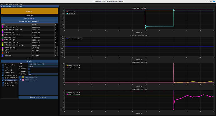
I seem to have found a bug in SimpleFOC in mode foc_current && velocity mode
For example, if the motor is at 20 rad/s
I do a motor.desable with commander and the ME0 command
then I do a ME1 (without having stopped the motor)
there’s a serious current peak

Hey,

if you call motor.disable() (ME0) then the current sense will not update unless you have modified the code to update them. This means your plot might be showing stale values while the motor is disabled.

Also the PID does not update while the motor is disabled, so when you re-enable it, it resumes from where it left off, but will find a very large delta-T.

when you call motor.enable(), with the target already set, then the behaviour may also depend on which is called first - loopFOC() or move() - if loopFOC() is called first, it will operate with whatever current target was set at the time motor.disable() was called. So you might want to adjust the target current in some way before enabling.
If move() is called first, it will calculate a new target voltage/current set-point for loopFOC, so perhaps it will help to make sure move is called before loopFOC(), despite the current value of motion_downsample

@runger
Thank you for your reply,
I tried to find the right order without success.

int old_motor_enabled;
float memory_max_current = motor.current_limit;

void loop() {
  old_motor_enabled = motor.enabled;
  motor.loopFOC(); // main FOC algorithm function
  command.run();

  current = currentSense.getPhaseCurrents();
  current_magnitude = currentSense.getDCCurrent(); // https://docs.simplefoc.com/inline_current_sense#example-code

  if (motor.enabled == 0) {
    command.run("M0 0\n");
  }

  if (motor.enabled == 1 && old_motor_enabled == 0) {
    String cmdSEND = "MLC" + String(memory_max_current) + "\n";
    command.run((char*)cmdSEND.c_str());
  }
  motor.move();
} // End loop

Connander send "ME0\n then after “ME1\n”

Have you tried resetting the pids before enabling the motor?

Keep in mind Current and Velocity pids are used in your case.

[EDIT] This is not resetting the timestamp though.

@Candas1
Tested this code without success, same current peak on motor.enabled

PhaseCurrent_s current;// getPhaseCurrents
float current_magnitude;
int old_motor_enabled;
float memory_max_current = motor.current_limit;

void loop() {
  old_motor_enabled = motor.enabled;
  motor.loopFOC(); // main FOC algorithm function
  command.run();

  current = currentSense.getPhaseCurrents();
  current_magnitude = currentSense.getDCCurrent(); // https://docs.simplefoc.com/inline_current_sense#example-code

  if (motor.enabled == 0) {
    command.run("M0 0\n");
    motor.PID_velocity.reset();
    motor.PID_current_q.reset();
    motor.PID_current_d.reset();
  }

  if (motor.enabled == 1 && old_motor_enabled == 0) {
    String cmdSEND = "MLC" + String(memory_max_current) + "\n";
    command.run((char*)cmdSEND.c_str());
    motor.PID_velocity.reset();
    motor.PID_current_q.reset();
    motor.PID_current_d.reset();
  }

  motor.move();

} // End loop

Hey, since you are in velocity mode, I would try something like this:

void loop() {
   bool is_enabled = motor.enabled;
   command.run();
   if (motor.enabled && !is_enabled) { // if we have a change in enabled state, reset the PID
    motor.PID_velocity.reset();
    motor.PID_current_q.reset();
    motor.PID_current_d.reset();
   }
   if (!motor.enabled) {   // in the disabled state, update the target to match the current velocity
      motor.target = motor.shaft_velocity;
   }
   motor.move();
   motor.loopFOC(); // loopFOC() after move, to make sure new targets are set
}

The idea being that when the motor is disabled, you update the target to match the motor’s current velocity. That way, when you re-enable the motor there is not a big delta in velocity.

@runger
Thanks for your answer,
I added a “current_magnitude” variable to monitor the currents in STMViewer.
There is still the current peak, and the motor makes 1/2 turn quickly before stopping when I do enable …

void loop() {
  bool is_enabled = motor.enabled;
  command.run();
  if (motor.enabled && !is_enabled) { // if we have a change in enabled state, reset the PID
    motor.PID_velocity.reset();
    motor.PID_current_q.reset();
    motor.PID_current_d.reset();
  }
  if (!motor.enabled) {   // in the disabled state, update the target to match the current velocity
    motor.target = motor.shaft_velocity;
  }
  motor.move();
  motor.loopFOC(); // loopFOC() after move, to make sure new targets are set
  current = currentSense.getPhaseCurrents();
  current_magnitude = currentSense.getDCCurrent();
}

EDIT:
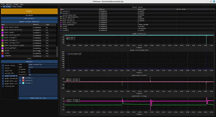
I have the impression that the problem is the same as with analogRead(),
related to a desynchronization of the current reading by ADC?

Out of curiosity, why are you disabling the motor while it’s spinning ?

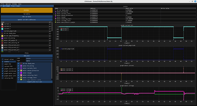
Interesting. Where are the sudden drops in current.b / current.c coming from?

I assume this is while the motor is disabled? And the peaks on the motor.current.d correspond to when the motor is enabled?

Yes, the peaks are when I activate the motor.
the graph above I send ME0 … then ME1

I’m just testing the features provided by SimpleFOC,
and the behavior of motor.desable|enabled (in foc_current) surprised me …