PWM input & 360 position control with AS5048A PWM Encoder

Hello, I’m newbie in Arduino world and FOC.

My first question is how can I implement PWM input control to SimpleFOC (so that PWM input from Radio Receiver or Pi’s output controls position & velocity of Brushless motor)–is there any way to connect PWM input to FOC shield?

Second, as you all know Arduino’s PWM library support only 180 degree of limited movement & position control of servo motors limited by 180 degree and other method of continuous rotation with modified servo which is basically open loop control of velocity that is useless for fine position control.

What I’ve been looking for is 360 degree of servo(Brushless motor) control in closed loop or zeroing out closed loop position control for multi rotation and looking at your video looks very promising and wondering whether it’s possible?

The project that I’ve been working on is; Pi4 running face detection program with OpenCV, Movidius Myriad X VPU for precessing acceleration(Pi4 alone is too slow & that’s why I needed this extra GPU power) and PWM output driving Simplebgc32 Gimbal, driving GBM8028-90T motors—following person’s face in almost realtime in silence for video conferencing.

And I have AS5048A PWM encoder attached to motor & controller hoping that may useful with FOC shield.

Problem with Stabilized gimbal controller is that it’s IMU(gyro) is always drift in static position that repetitive position control is not possible even with Magnetometer.

And I believe SimpleFOC is the one I’ve been looking for.

Here is my project video link;

Look forward for community input & thank you much for sharing great project!

Hey Martin,

Great project :slight_smile:
What you need will be easy to implement with an Arduino and a SimpleFOCshield. There’s a few different ways you could read a PWM signal with the arduino, but from what I gather you really don’t need this as your Pi4 could talk to the Arduino through a serial communication protocol.

If you’re adamant about using a PWM signal for communicating the desired position I would recommend you give this a try to read the PWM signal and afterwards you would just have to translate your readings to a value between 0 and 2PI (around 6.28 radians): https://www.camelsoftware.com/2015/12/25/reading-pwm-signals-from-an-rc-receiver-with-arduino/

If you already have a Shield try the open loop example, then the closed loop example and let us know how it goes; we should be able to help you from there :slight_smile:

DGR,

Thank you much for real fast response!

I’m not adamant about using PWM but rather I don’t know much about coding in Arduino & Python.—Totally Newbie & can not or don’t know how to modify given code to suit my need—.

Naturally, I have to work with what is available for me to put things together with numerous research with minimal knowledge and try & error basis, without knowing what may work and may not, based on real scientific knowledge, and of course caused me to purchase bunch of stuff & testing plus disappointment.

My project was started to help people who can not stay still in front of video camera for video conferencing with their loved ones and does not recognize the importance of necessity being in the center of video camera centroid focal point and scared by servo gear noise, delayed response video reaction, high pitched brushless gimbal noise once in a while when sudden position changes.

I’ve used Adrian’s blog to implement Face Tracking, Deep Learning and Movidius implementation as I referred in my Youtube video, exception of Tensorflow adoption per Leigh jones that I could never make it work with Raspberry Pi4 due to coding incompatibility & complexity of Tensorflow implementation to Pi 4 about 1 or 1.5 year ago.

Adrian’s original python code & modified code version is based on PWM output & I don’t have any idea how to convert it to other format or method.

Main Python Code (Before Movidius) is provided as follows;# USAGE

python detect_faces_video.py --prototxt deploy.prototxt.txt --model res10_300x300_ssd_iter_140000.caffemodel

import the necessary packages

from imutils.video import VideoStream
import numpy as np
import argparse
import imutils
import time
import cv2
from imutils.video.pivideostream import PiVideoStream
from pantilthat import *

construct the argument parse and parse the arguments

ap = argparse.ArgumentParser()
ap.add_argument(“-p”, “–prototxt”, required=True,
help=“path to Caffe ‘deploy’ prototxt file”)
ap.add_argument(“-m”, “–model”, required=True,
help=“path to Caffe pre-trained model”)
ap.add_argument(“-c”, “–confidence”, type=float, default=0.5,
help=“minimum probability to filter weak detections”)
args = vars(ap.parse_args())

load our serialized model from disk

print(“[INFO] loading model…”)
net = cv2.dnn.readNetFromCaffe(args[“prototxt”], args[“model”])

Default Pan/Tilt for the camera in degrees.

Camera range is from -90 to 90

cam_pan = 90
cam_tilt = 60

initialize the video stream and allow the cammera sensor to warmup

print(“[INFO] starting video stream…”)
vs = PiVideoStream(vf=True,hf=False,framerate=25).start()
time.sleep(2.0)

Turn the camera to the default position

pan(cam_pan-90)
tilt(cam_tilt-90)

FRAME_W = 320
FRAME_H = 240

loop over the frames from the video stream

while True:
# grab the frame from the threaded video stream and resize it
# to have a maximum width of 400 pixels
frame = vs.read()
frame = imutils.resize(frame, width=400)

# grab the frame dimensions and convert it to a blob
(h, w) = frame.shape[:2]
blob = cv2.dnn.blobFromImage(cv2.resize(frame, (300, 300)), 1.0,
	(300, 300), (104.0, 177.0, 123.0))

# pass the blob through the network and obtain the detections and
# predictions
net.setInput(blob)
detections = net.forward()

# loop over the detections
for i in range(0, detections.shape[2]):
	# extract the confidence (i.e., probability) associated with the
	# prediction
	confidence = detections[0, 0, i, 2]

	# filter out weak detections by ensuring the `confidence` is
	# greater than the minimum confidence
	if confidence < args["confidence"]:
		continue

	# compute the (x, y)-coordinates of the bounding box for the
	# object
	box = detections[0, 0, i, 3:7] * np.array([w, h, w, h])
	(startX, startY, endX, endY) = box.astype("int")

	# draw the bounding box of the face along with the associated
	# probability
	text = "{:.2f}%".format(confidence * 100)
	y = startY - 10 if startY - 10 > 10 else startY + 10
	cv2.rectangle(frame, (startX, startY), (endX, endY),
		(0, 0, 255), 2)
	cv2.putText(frame, text, (startX, y),
		cv2.FONT_HERSHEY_SIMPLEX, 0.45, (0, 0, 255), 2)

    # Track first face

    # Get the center of the face
	x = (startX+endX)/2
	y = (startY+endY)/2

    # Correct relative to center of image
	turn_x  = float(x - (FRAME_W/2))
	turn_y  = float(y - (FRAME_H/2))

    # Convert to percentage offset
	turn_x  /= float(FRAME_W/2)
	turn_y  /= float(FRAME_H/2)

    # Scale offset to degrees
	turn_x   *= 2.5 # VFOV
	turn_y   *= 2.5 # HFOV
	cam_pan  += turn_x
	cam_tilt += turn_y

	print(cam_pan-90, cam_tilt-90)

    # Clamp Pan/Tilt to 0 to 180 degrees
	cam_pan = max(0,min(180,cam_pan))
	cam_tilt = max(0,min(180,cam_tilt))

    # Update the servos
	pan(int(cam_pan-90))
	tilt(int(cam_tilt-90))


# show the output frame
cv2.imshow("Frame", frame)
key = cv2.waitKey(1) & 0xFF

# if the `q` key was pressed, break from the loop
if key == ord("q"):
	break

do a bit of cleanup

cv2.destroyAllWindows()
vs.stop()

Hey Martin,

That sounds like most of us :smiley:

I used to follow Adrian and he has a lot of cool projects and tutorials. I think Tensorflow is probably over-kill for face detection. From the code you attached I can see the “pantilthat” library is used and I’m guessing you’re not using the “Hat” and this is just to generate the PWM signals. We could leave this like that and work on the Arduino side of things. Have you gotten an Arduino (or another microcontroller) and a SimpleFOCshield (or another driver) yet?

I love the goal of the project and I’m happy to help.

David

David,
Thank you! You are right and I used pan & tilt hat over Pi4 and used that PWM output signals as RC input signal to Simplebgc 32 board to drive large brushless motor.

I tried both Google’s Coral stick & Intels Movidus and concluded that Myriad running on Pi4 with OpenCV+Caffe Latte is much faster, recognize face in different angles than the Tensorflow with less trouble.

SimpleFOC Shop is currently out of stock for shield and I could not find other available driver in the Google and of course I have plenty of Arduinos around.

I came across Pablo’s Youtube where he explained his FOC control method; https://youtu.be/MKNkZOja7-s
and ordered couple of his development board which I think using same driver chip for FOC control. and I also suggested him to implement PWM input method as well.

I’m looking forward experimenting with both method upon delivery and hope PWM input control method is available soon (I would think there would be demand; due to quite, precision servo control & great for robotic project like) and I also see this brushless motor position control method may provide continuous position control over 360 degree rotation by zeroing out each 1 turn, (Arduino & Pi’s PWM is only provide 180 degree maximum position control in closed loop as you know)

Sincerely

Martin,

I’ve seen Pablo´’s board, it’s going to work just fine. it’s basically an Arduino with MOSFETS all in one. Though his code will be much less efficient and less precise than what is possible with the SimpleFOC library. You should be able to flash whatever code you want to the board.

Don’t worry about the PWM implementation it will be easy to do even if this signals usually only position 180 degrees in the RC world. We can manipulate this signal in the Arduino side of things and leave the python code as is. Let me know when you get your boards.

David,

Much appreciated your kindness!

Just ordered Pi4 8GB and 500GB NVMe SSD to speed things up (4GB Pi4 was like pushing the limit constantly exceeding 85% of CPU memory usage & got pretty hot to the point of hang & freeze even with cooling case & fan over.

I’m hoping this new set-up with FOC controller will provide closer to real time face recognition & tracking response and also looking for ways to put motor controller in a sleep mode (to prevent overheating of brushless motor)–Pi4 do not have sleep mode & hoping to find that possibility on Arduino side in meantime.

I’ve tried Odroid XU4, Pi3, Dragon Board 1410C, Windows Tablets and so far Pi4 is in the top, in terms of price point, resource affordability and feasible practical usability.

Nvidia platform, of course will break my wallet and more white hair.

I think that use of higher resolution optical encoder will definitely help for precision positioning over magnetic encoder at the cost of processing power & latency and I’m hoping zeroing-in closed loop control method would be incorporated so that motor would not need to rotate 360 degree to be positioned back to same 0 degree or make unnecessary farther movement.

Another word, if target position is clockwise 3:00 that radiant angle is 90 degree, when Processing interpret that as 270 degree vs 90 degree would make big difference in processing resources and latency.

Hey Martin,

Happy to help :slight_smile:

I think maybe the recognition could be improved so your Pi can handle the program. I’ve never used a Movidius stick, what are the changed needed on the program to use it?

Have you tried something like haar-cascades for face recognition that should be much less demanding? If not, give this a try and if you think it will be suitable we can then adapt some code for the PWM signals. Face Detection in 2 Minutes using OpenCV & Python | by Adarsh Menon | Towards Data Science

With the SimpleFOC library you can disable the motors and this could simulate sleep mode you’re talking about. I’m not sure how important this is to you.

I disagree about the optical encoder being better for precise positioning. I’ve haven’t done a side to side comparison, but I would imagine they perform very similar (comparing a same resolution magnetic encoder to an optical one). Personally, I prefer magnetic encoders because they are cheap, compact, very easy to use and have been very precise for my applications. Furthermore, most magnetic encoders are absolute so as soon as you power the system you know where you’re at.

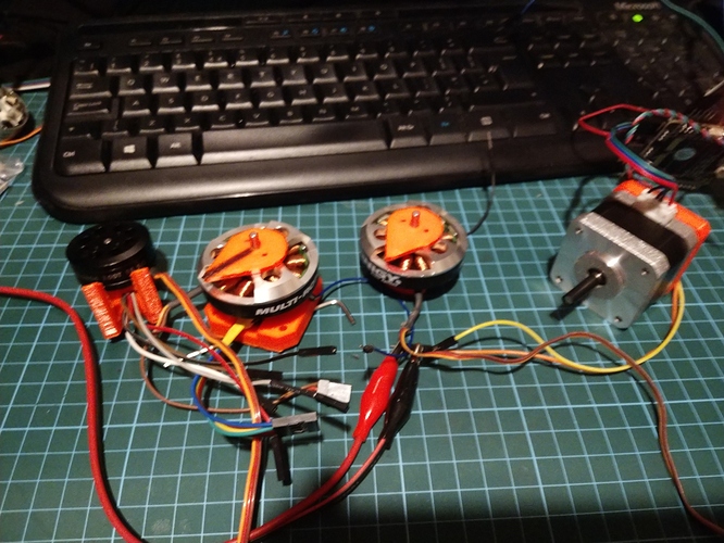
I agree on magnetic sensor. They are also often easier to fit 1. the diametric magnet is glued on to the backside of the motor. 2. I 3d print a shim to hold the board (e.g as5047) 2 mm away from the magnet. The shim is screwed into the stator of the motor.
Some examples, the 3rd motor has the sensor removed so you can see the magnet:


David,
It may have been Simplebgc32 board’s IMUs & gyro drift that lead me to think it may not as accurate as optical sensor (my Roboteq BLDC controller with optical encoder was solid steady on my experiment it was just too big and very expensive for this project).

Haar-cascades method is much faster & less demanding for sure but it can not recognize partial face such; face turned to side, upward, downward and very sensitive to back ground lighting hence face recognition rate is only about 25 to 30% in average.

Deep learning method using Myriad processing(Intel Movidius) at close range (less than 5’) using webcam is about 80 to 90% in average and it also detect partial face, if person wear mask it drop down to about 50% & I’ve put that on future issue together with sleep mode.

Adrian have this Deep Learning & Movidius implementation in following links & that’s what used(He also have Pan & Tilt PID control loop but I had to hold off on that since I Cann’t fine tune PID on Brushless motor controller);

Code from my working Pi4 (including all above & shown on my YouTube video) is follows;

USAGE

python facetracker_caffe_test.py --prototxt deploy.prototxt.txt --model res10_300x300_ssd_iter_140000.caffemodel

import the necessary packages

from imutils.video import VideoStream
import numpy as np
import argparse
import imutils
import time
import cv2

from imutils.video.pivideostream import PiVideoStream #MK–Original

from imutils.video import VideoStream #MK–Changed for USB Cam–both org & mk change works for webcam

from pantilthat import *

construct the argument parse and parse the arguments

ap = argparse.ArgumentParser()
ap.add_argument(“-p”, “–prototxt”, required=True,
help=“path to Caffe ‘deploy’ prototxt file”)
ap.add_argument(“-m”, “–model”, required=True,
help=“path to Caffe pre-trained model”)
ap.add_argument(“-c”, “–confidence”, type=float, default=0.5,
help=“minimum probability to filter weak detections”)
args = vars(ap.parse_args())

load our serialized model from disk

print(“[INFO] loading model…”)
net = cv2.dnn.readNetFromCaffe(args[“prototxt”], args[“model”])

specify the target device as the Myriad processor on the NCS

net.setPreferableTarget(cv2.dnn.DNN_TARGET_MYRIAD)

Default Pan/Tilt for the camera in degrees.

Camera range is from -90 to 90

cam_pan = 90
cam_tilt = 60 #original was 60

initialize the video stream and allow the cammera sensor to warmup

print(“[INFO] starting video stream…”)
vs = VideoStream(src=0).start() #MK–this for default cam

vs = VideoStream(usePiCamera=True).start() #MK–this for picam & org

time.sleep(2.0) #original was (2.0)

Turn the camera to the default position

pan(cam_pan-90)
tilt(cam_tilt-50) #original was 60

FRAME_W = 320
FRAME_H = 240

FRAME_W = 640 # MK–tried & no diffirence

FRAME_H = 480

loop over the frames from the video stream

while True:
# grab the frame from the threaded video stream and resize it
# to have a maximum width of 400 pixels
frame = vs.read()
frame = imutils.resize(frame, width=400)

# grab the frame dimensions and convert it to a blob
(h, w) = frame.shape[:2]
blob = cv2.dnn.blobFromImage(cv2.resize(frame, (300, 300)), 1.0,
    (300, 300), (104.0, 177.0, 123.0))

# pass the blob through the network and obtain the detections and
# predictions
net.setInput(blob)
detections = net.forward()

# loop over the detections
for i in range(0, detections.shape[2]):
    # extract the confidence (i.e., probability) associated with the
    # prediction
    confidence = detections[0, 0, i, 2]

    # filter out weak detections by ensuring the `confidence` is
    # greater than the minimum confidence
    if confidence < args["confidence"]:
        continue

    # compute the (x, y)-coordinates of the bounding box for the
    # object
    box = detections[0, 0, i, 3:7] * np.array([w, h, w, h]) #MK Changed this & error
    (startX, startY, endX, endY) = box.astype("int")
    #box = detections[0, 0, i, 3:7] * np.array([w, h, w, h]) #original 
    (startX, startY, endX, endY) = box.astype("int")

    # draw the bounding box of the face along with the associated
    # probability
    text = "{:.2f}%".format(confidence * 100)
    y = startY - 10 if startY - 10 > 10 else startY + 10
    cv2.rectangle(frame, (startX, startY), (endX, endY),
        (0, 0, 255), 2)
    cv2.putText(frame, text, (startX, y),
        cv2.FONT_HERSHEY_SIMPLEX, 0.45, (0, 0, 255), 2)

    # Track first face

    # Get the center of the face
    x = (startX+endX)/2
    y = (startY+endY)/2

    # Correct relative to center of image
    turn_x  = float(x - (FRAME_W/2))
    turn_y  = float(y - (FRAME_H/2))

    # Convert to percentage offset
    turn_x  /= float(FRAME_W/2)
    turn_y  /= float(FRAME_H/2)

    # Scale offset to degrees
    turn_x   *= 2 # VFOV --MK Changed this from 2.5
    turn_y   *= 3.5 # HFOV
    cam_pan  += turn_x # use -turn_x for reversing
    cam_tilt += turn_y

    print(cam_pan-90, cam_tilt-90)

    # Clamp Pan/Tilt to 0 to 180 degrees
    cam_pan = max(0,min(180,cam_pan))
    cam_tilt = max(0,min(180,cam_tilt))

    # Update the servos
    pan(int(cam_pan-90))
    tilt(int(cam_tilt-90))


# show the output frame
cv2.imshow("Frame", frame)
key = cv2.waitKey(1) & 0xFF

# if the `q` key was pressed, break from the loop
if key == ord("q"):
    break

do a bit of cleanup

cv2.destroyAllWindows()
vs.stop()

Cheers!

Thank you Owen!

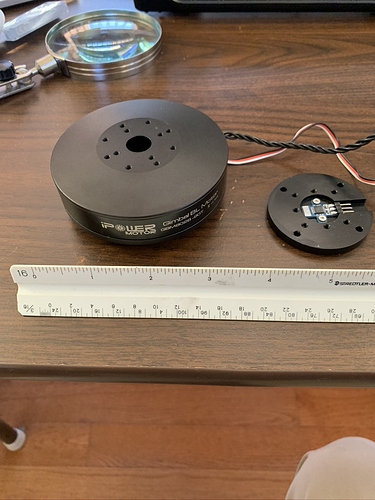
My powerful motor setup(36N42P) that I’ve used on my project, I think encoder is AS5048A


Martin,

You’ve done a lot of research and tests so let’s hope the Extra RAM will do the trick. I see the code is pretty much the same so that is good news. From here let’s wait for your controllers to arrive and get your brushless motors working properly in closed loop and afterwards we will do the implementation of the two systems. I should be free to skype one of these days if you need help or just to chat :slight_smile:

With those motors you’ve got the perfect setup to get SimpleFOC running smoothly.

David,

Thank you much!, expecting shipment in about two week.

I’ve also came across with Justine Haupt here & looks like she got almost everything including PWM input but no Magnetic encoder implementation (I left message about feasibility); https://youtu.be/OZvjfbpXpro

I think Justine, Pablo and Simple FOC will make great team in terms of affordable yet advanced motor controller product packaged development and substantial business growth perspective additionally going forward with 32bit processing power, initially toward Adurino & Pi community.

I’ve seen her board and I find it very cool, but a bit expensive.

An advantage of this platform being based on Arduino and completely open-source is that you can implement the communication protocol you want and have the same result. This is why I tell you to not worry a lot about the PWM or any communication protocol as this is will be able to be done whatever way we want.

True, in comparison with Simple FOC(Single channel, stackable design over Arduino and rather may be bulky for 2 or more channel application) & Pablo’s board(Dual Channel, require boot loader install from end user but somewhat require small foot print & slim) but all are still cheaper than Odrive or Roboteq’s although they were primarily aimed toward high power & higher RPM application and based on 32bit processor.

By the way, I think her design & code are all open source and used Mega2560 although I was hoping that to be 32bit.

She does already have pretty good motor design & appears already have supply chain sourcing for mass production stage for both controller and customized higher quality motor :slightly_smiling_face:

I think you’ve all established great motor control method & perhaps possible capability for positioning control like this kind motor; [PDF] Improvements of Performance of Multi-DOF Spherical Motor by Double Air-gap Feature | Semantic Scholar

1 Like

Have you seen my custom board? https://community.simplefoc.com/t/esp32-brushless-controller-dagor-work-in-progress/132/12

Cool! I’m definitely in the right place!

David,

I’ve received board from Pablo (which I think it’s older version of BGC32) & flashed it for Arduino code. and also got Pi4 with 8GB, setup with Tensorflow face tracking with PID tested and also setup with OpenVINO face tracking with PID for comparison. turns out Tensor provide much better accuracy(face detection) and smoother tracking.

I’ve searched Simple FOC’s code for closed control loop and I could not find it, looking at Pablos code I saw “closed_loop_double_youtube_board.ino” which was written to run 2 brushless motors in closed loop mode as a Steer-by-Wire and this is link;
https://github.com/juanpablocanguro/BRUSHLESS-MOTORS/blob/master/closed_loop_double_youtube_board.ino

I think this code is good start since it already have 2 motor control loop but looking at code, I have no idea what to change or modify to use with 2 PWM input for independent motor position control.

Kindly help or input will be deeply appreciated!

Hey @Martin-Kim,

Glad to hear back form you. I wouldn’t use Pablo’s code because it’s not efficient and your motor will most likely get hotter because of the way he does position control. Here you can find the SimpleFOC closed loop example for using a magnetic sensor to close the loop:

Try running this code for one motor and tune your PID controller, be careful with the pins you’re using on Pablo’s board. I’ll help you set up then for the two motors and then for the PWM inputs :slight_smile:

David,

Thank you so much & I’ll try to figure out pins and work on PID