David,
The magnetic sensor that I have is AS5048A with PWM output and I’m wondering it doesn’t get support from this code?
I got it, it was under analog!
David,
The magnetic sensor that I have is AS5048A with PWM output and I’m wondering it doesn’t get support from this code?
I got it, it was under analog!
Can you use the SPI bus of the AS5048A? if yes the code should work by writing any pin on your microcontroller you’re not using and connecting it to the “CSn” of the AS5048
Replace 10 by the pin you want to use
csnPin = 10;
MagneticSensorSPI sensor = MagneticSensorSPI(csnPin, 14, 0x3FFF);
Analog should work too, give it a go and let me know if it works.
David,
SPI is too tight for me solder new wire connection & I tried with “MagneticSensorAnalog sensor = MagneticSensorAnalog(A1, 14, 1020);” and “BLDCMotor motor = BLDCMotor(9, 10, 11, 24, 8);” since I have 48 pole motor
but motor is not turning at all upon any target angle input ( I tried with different P of 1 and max voltage of 10 & result were same), my power supply is 12Volt 19 AMP unit with circuit breaker of 2 AMP connected.
Perhaps it’s because Pablo’s new board that I’m using is not L6234 based?
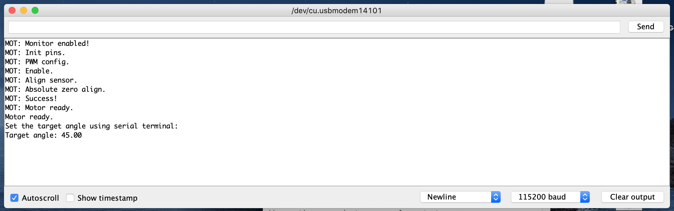
Here is my Serial output;
And this is what I upload into Pablos’s board or Arduino within(code per your link) & Simple FOC board is still out of stock for me to try;
/**
*
*/
#include <SimpleFOC.h>
// magnetic sensor instance - SPI
// MagneticSensorSPI sensor = MagneticSensorSPI(10, 14, 0x3FFF);
// magnetic sensor instance - MagneticSensorI2C
// MagneticSensorI2C sensor = MagneticSensorI2C(0x36, 12, 0x0E, 4);
// magnetic sensor instance - analog output
MagneticSensorAnalog sensor = MagneticSensorAnalog(A1, 14, 1020);
// BLDC motor instance
BLDCMotor motor = BLDCMotor(9, 10, 11, 24, 8);
// Stepper motor instance
//StepperMotor motor = StepperMotor(9, 5, 10, 6, 50, 8);
void setup() {
// initialise magnetic sensor hardware
sensor.init();
// link the motor to the sensor
motor.linkSensor(&sensor);
// power supply voltage
// default 12V
motor.voltage_power_supply = 12;
// choose FOC modulation (optional)
motor.foc_modulation = FOCModulationType::SpaceVectorPWM;
// set motion control loop to be used
motor.controller = ControlType::angle;
// contoller configuration
// default parameters in defaults.h
// velocity PI controller parameters
motor.PID_velocity.P = 0.2;
motor.PID_velocity.I = 20;
motor.PID_velocity.D = 0;
// maximal voltage to be set to the motor
motor.voltage_limit = 6;
// velocity low pass filtering time constant
// the lower the less filtered
motor.LPF_velocity.Tf = 0.01;
// angle P controller
motor.P_angle.P = 20;
// maximal velocity of the position control
motor.velocity_limit = 20;
// use monitoring with serial
Serial.begin(115200);
// comment out if not needed
motor.useMonitoring(Serial);
// initialize motor
motor.init();
// align sensor and start FOC
motor.initFOC();
Serial.println(“Motor ready.”);
Serial.println(“Set the target angle using serial terminal:”);
_delay(1000);
}
// angle set point variable
float target_angle = 0;
void loop() {
// main FOC algorithm function
// the faster you run this function the better
// Arduino UNO loop ~1kHz
// Bluepill loop ~10kHz
motor.loopFOC();
// Motion control function
// velocity, position or voltage (defined in motor.controller)
// this function can be run at much lower frequency than loopFOC() function
// You can also use motor.move() and set the motor.target in the code
motor.move(target_angle);
// function intended to be used with serial plotter to monitor motor variables
// significantly slowing the execution down!!!
// motor.monitor();
// user communication
serialReceiveUserCommand();
}
// utility function enabling serial communication with the user to set the target values
// this function can be implemented in serialEvent function as well
void serialReceiveUserCommand() {
// a string to hold incoming data
static String received_chars;
while (Serial.available()) {
// get the new byte:
char inChar = (char)Serial.read();
// add it to the string buffer:
received_chars += inChar;
// end of user input
if (inChar == ‘\n’) {
  // change the motor target
  target_angle = received_chars.toFloat();
  Serial.print("Target angle: ");
  Serial.println(target_angle);

  // reset the command buffer
  received_chars = "";
}
}
}
I think it is a smart idea to try to move the motor open loop first with your new board. Try this example:
If you tell it to move 6.28 rads it should spin exactly one revolution, if it doesn’t it means your pole pair number is wrong.
David,
I’ve uploaded this code;
https://github.com/juanpablocanguro/BRUSHLESS-MOTORS/blob/master/Closed_loop_haptic_modes_youtube
to make sure my board is working & find my pin connections are correct.
Although it tremble a lot, it worked to the extent that I at least know two motors and magnetic PWM input pins are connected correct.
I ran FOC open loop test by changing “BLDCMotor motor = BLDCMotor(9, 10, 11, 21, 8);”—you were correct my motor was 42pole but this didn’t run.
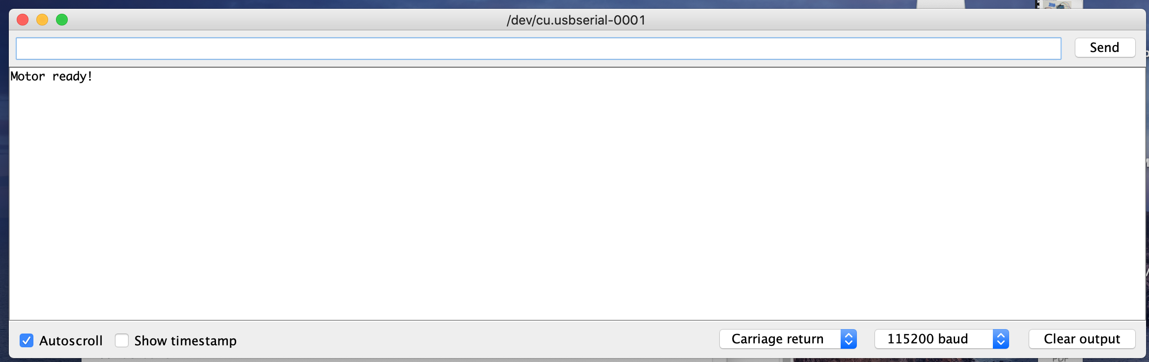
I see “Motor ready!” on serial terminal, I entered 6.28 and nothing happens and one motor at 9,10,11 is energized & not rotating
Do you feel like one coil of the motor is energized when you try to make it rotate? This feels like it really wants to stay in a position and spinning the rotor with your hand feels like the motor has “steps”.
Try changing the motor.voltage_limit = 3; to something higher. If you could attach a video of the behavior you’re experiencing I should be able to help more ![]()
David,
Changed voltage to 6, once power is on that motor on 9,10,11 pins are energized (It won’t turn by hand easily but turn in small step upon good force)
Okay, that means it’s trying to hold it’s position. Does it try to do something when you change the position?
Try changing motor.velocity_limit = 20; to something like 1 rad/s.
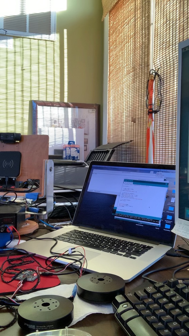
Same thing with 1, entered “6.28” & it won’t move. I tried copy & paste mov file here it won’t work, so here is jpg.
This is very weird. Maybe try with the 3, 5 and 6 pins instead of 9, 10, 11. Do you know if Juan Pablo has published the schematic of the board?
I already tried 3,5,6 & same thing, would it because of Pablo used Alpha & Omega Chip AO4606? or that doesn’t matter?
I saw that on this video https://www.youtube.com/watch?v=VPeVrJcTTNg
That shouldn’t be a problem. When you try to move does the Serial monitor prints “Target position: ___”?
Try this:
BLDCMotor motor = BLDCMotor(9, 10, 11, 21);
Hi guys,
Maybe i just read the thread too quickly but as I understand you would like to use a PWM output of the sensor. This is not supported by the library at the moment. Analog input is not a PWM input and it will not work.
This type of sensor is not too difficult to implement but it is not too common so we are procrastinating to implement it ![]()
Can you try a sensor example in utils folder. Make sure that this works before starting any control loop.
Hey @Antun_Skuric,
I didn’t realize that PWM wasn’t supported yet, if it comes down to it I’ll help with the implementation. We’re firstly trying to do open_loop control, but it seems @Martin-Kim is having issues. He feels these “steps” while trying to rotate it by hand as the motor is trying to hold it’s position, but when he changes the setpoint nothing seems to happen.
Thank you all!
I tried “BLDCMotor motor = BLDCMotor(9, 10, 11, 21);” and same thing, it won’t move at all, I don’t see “Target position: ___”?
I was wondering about that Analog, I always thought PWM was digital.
I’ll try sensor example
If you don’t see “Target position: ___” after writing something on the console the motor is not moving because it doesn’t see the instruction. There might be something wrong with your Serial monitor or usb connection (which is unlikely). Con you share a screenshot of the serial monitor after initialization and after you give it a numerical value to move to?
Sure can, let me know when you ready & how.
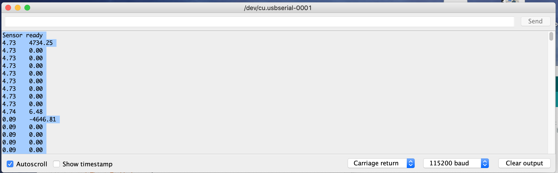
I just ran this test
https://github.com/simplefoc/Arduino-FOC/tree/master/examples/utils/sensor_test/magnetic_sensors/magnetic_sensor_analog_example
It doesn’t detect rotation rather just bunch of numbers flowing down;
And this is screen shot after initialization & same screen after 6.28 value entered
Working!!! I changed Carriage return to Both NL & CR
and it’s 1 turn
As @Antun_Skuric explained we would have to implement the PWM sensor, as of right now already implemented are SPI. Let’s forget about the sensor for a second and keep trying open loop control.
There seems to be a problem with the input of instructions. Are you sure you’re calling serialReceiveUserCommand(); in the void loop?
Try replacing the serialReceiveUserCommand() function and let’s see if something print when you try to send an instruction.
void serialReceiveUserCommand() {
  // a string to hold incoming data
  static String received_chars;

  while (Serial.available()) {
    Serial.println("Input received");
    // get the new byte:
    char inChar = (char)Serial.read();
    // add it to the string buffer:
    received_chars += inChar;
    // end of user input
    if (inChar == '\n') {

      // change the motor target
      target_position = received_chars.toFloat();
      Serial.print("Target position: ");
      Serial.println(target_position);

      // reset the command buffer
      received_chars = "";
    }
  }
It’s working after I changed Carriage return to Both NL & CR and rotated 1 turn with message
Motor ready!
Target position: 6.28
Also noticed one of chip on board getting hot(I’m guessing my power supply is too big for this at 19Amp)
![]() I don’t know why I didn’t think of that earlier, I’ve had that happen to me countless times. Glad it’s working now.
I don’t know why I didn’t think of that earlier, I’ve had that happen to me countless times. Glad it’s working now.
Lower the voltage limit! Find a value where the board isn’t hot or is reasonably hot. Open-loop is much more less efficient than closed-loop so once you close the loop this should improve. I’m sorry we don’t have PWM input implemented just yet. If you can’t use the SPI bus, I’ll let you know once we implement PWM input.