@Owen_Williams I have some boards with no components and those boards show no problems with shorts, so I that would discard a manufacturing problem.
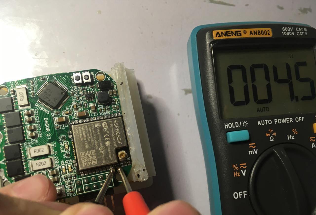
I got 5 boards with no components and 5 boards with all the components minus the ESP32, the AS5147P, the buttons and the inductor (as seen in the picture with the coin).
My guess is that something is happening under the ESP32 and I can’t see it. My soldering skills are not the best, but I always make sure there are no shorts and clean everything with alcohol. I’m considering a short something that shows <100 ohms on the multimeter, a pin with no short will usually show a resistance of around 100kohm or even megaohms with any other pin. With 3 of my boards and five different ESP32s I’ve had these shorts that are not visible and that type of weird - inconsistent behavior. I just realized that these shorts have happened on other pins between neighbor pins on the ESP32. I believe this has been the root of all my problems, bad bootstrap pin status, bad SPI communication, bad communication with PC, etc.
Would anybody have a recommendation to avoid this? I’m open to skype if somebody wants to chat
My colleague said (he is responsible for the hardware circuit), your PCB layout is too compact, this layout can only be overcome by a real top EMC / EMI master!
His suggestion is to abandon the “5047” on board and rearrange the PCB with the free space.
I have a very similar board and here are my thoughts.
The GND pad on your board under the ESP-32 WROOM looks too big. Mine is 3.5x3.5mm
My pads are 1.45x0.86mm
ESP-32 IO12 needs a pull down
I had to use a 100 Ohms resistor between ESP-32 SPI-CLK and the AS5147
I didn’t use flux when soldering on the ESP-32 WROOM.
I used as little heat as possible. I didn’t want to melt the solder on the inside of the Module.
I soldered all the components by hand (your board is a lot cleaner)
Did you get your ESP-32 WROOM board from Mouser?
I hope this helps
You’re right my GND pad is too big, I was considering getting rid of it altogether as it’s not a requirement and I never solder it. My pads are 2x0.72mm
I’ve monitored the state of IO12 and it’s pulled down always as I don’t use this pin. I’ve added an external pull-down with no different behavior.
What’s the reason behind not using flux? I was starting to think that maybe I’m doing something horribly wrong with my soldering and this is the reason I’m having so many problems.
I got my ESP32 from LSCS electronics, I got ESP32 WROOM 32D and 32U.
Flux could be getting inside the metal can and/or too much heat could cause problems inside the can. Your 32U looks different from mine but LSCS is a reputable company so it will not be a fake module. I also put a layer of silkscreen under the WROOM module to make sure there weren’t any shorts.
After further testing I’ve concluded that all my issues have been because of the ESP32 wroom module assembly. Every time I notice the board behaving strangely I’ll find with a multimeter a set of neighbor pins on the ESP32 that seem shorted when they were previously not.
For example, one time communication seemed to stop working so I grabbed my multimeter and found TX0 and RX0 shorted after days of having worked properly.
The shorts always seem to come back when I’m using the board. If I leave it unused for a few days no short will appear. I’ve been reading online and I think I have some sort of contamination on my board that will produce dendrites or something similar when operating. This could have been cause because of bad quality solder, flux or alcohol.
Would you guys please recommend me brands for all of the above that you have tested and have gotten good results in the past? Thank you.
@Gouldpa I’ll definitely keep your recommendations in mind when assembling another board, thank you.
What is the status of your dagor board? Have you fixed most of the issues? Were they soldering problems? Is it possible to build / buy one of these yet?
All the issues were because of the soldering. Given there are no visible shorts I still have problems with shorts that will randomly appear on some pins and I’ll notice because the board will start to behave weirdly. I’ll say the issue is totally resolved once I assemble a board and have no problems. I’m thinking on changing everything: solder, flux, soldering iron tip, solder wick and try with a new board to see if that does the trick.
Not yet, I’m thinking on doing a few improvements, like changing the buck converter - but I haven’t decided.
So so so easy, it’s quite surprising how easy it is to get working. With the motor.command() function that @Antun_Skuric implemented I just have to send and read a String.
I like what I am seeing, I have a few questions and suggestions.
Why did you choose to put the encode on the board? I think that applications off this board will often have the need of an external encode like the AS5600 (I²C), maybe make it so you can choose?
Why did you choose the ESP32 as the microcontroller?
I put the encoder on the board because it’s intended to be small and close to the motor so I can make a compact actuator. If you look at the back of the board you can see I left some pins for an external SPI bus or an i2c bus.
Because of it’s connectivity options, community and arduino compatibility; though it’s been a challenge to use. I’m looking forward to use ESP-NOW for a lot of my proyects and I just like the idea of having no wires. You can check out an ESP-NOW demo above.
There is no need to ignore the copper thickness. If you are using standard pooling thickness for prototypes and plan on maybe 105um, you may be able to achieve half the switches rating. The heat is the limiting factor, and if your traces cant cope with the current flow, it will heat up your components and thereby add to the Rds(on). What is your trace width and copper thickness going to the MOSFETS. To use 105um copper there is a minimum 0.25mm trace width and likewise clearance.
Edit: As you may know, internal layers is quite poor at dissipating heat, therefore it is misleading to just write “its a 4 layer pcb”. I think the ground trace must be equally wide/thick.
I’m doing a small Alpha run of the board soon. Please fill this google forms if you’re interested so I can have an idea on how many boards I should have ready:
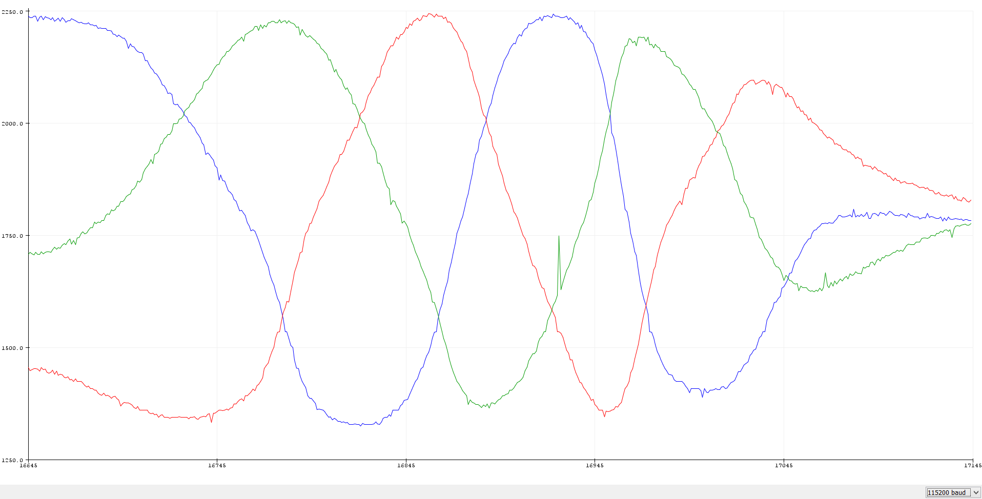
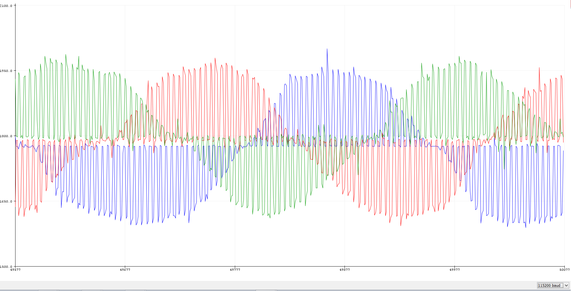
As it has been discussed on the forum before, the Dagor Controller uses a low-side shunt resistor for current sensing, this posed a challenge to sync the ADC measurement with the on-time of the low-side FET of each phase. With the ESP32’s MCPWM unit I managed to do this and get good current readings.


")