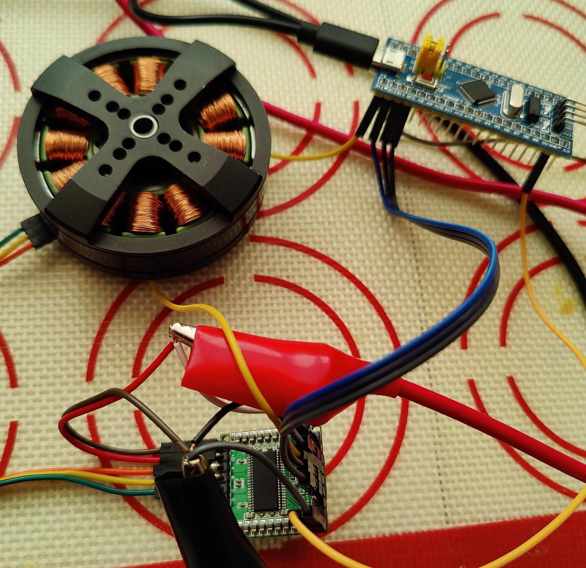
As the title says. Versatile Quad-PWM driver, capable of running two brushed DC motors, one BLDC or one stepper. Takes input from 4 PWM or 3 PWM logic, which means it could run with pretty much any MCU out there, PWM up to 500kHz. Which means you could experiment and test with them all using only one driver. Even better, since it requires only up to 4PWM, you can pair two of these with one MCU and drive 4 DC brushed motors independently for a 4-wheeled quad-powered platform with independent wheel control, or two brushless.
The driver itself is not new, but this board hasn’t seen it in action. Think of it as the Swiss Knife of drivers.
This is just my breakout test board. More to come later.
I’m planning to build a small board similar to the Mosquito. Size would be about 25 x 25mm. Got to think of a cool name first. It’s all about the name.
We could also look at using the 4th channel for active braking BLDCs, or some other purpose. At 500kHz it would be enough for DC conversion too, I think. I have to look at the datasheet.
I’m new to cutting edge drivers – out of curiosity - how is this driver sourced? Did you receive a sample of 1 or 2 IC’s from the manufacturer? I checked a couple vendors and it seemed either out of stock or having a ship date 1 year out. I saw a dev board, but that was close to $200. Does it usually work that they make an announcement and provide samples, and then the developers and community take a significant bit of time to evaluate before knowing if the IC has potential?
Pay money to the supplier (LCSC/JLC). I have not yet found any supplier willing to send me freebees.
Well the driver is $15 and the dev breakout board is extremely simple with only a few capacitors and resistors, so probably $20 with everything. Wow, that’s 10x more expensive. Hey if you can sell it at $190 I can manufacture it and sell it to you at $100, this way we both make money! I’m joking obviously.
As I said never seen free samples. Usually I design the PCB, then order it and test if it works, then go and party. Developing a simple board like that takes may be couple hours so not really significant amount of time. Testing is may be an hour, may be more if you want to burn one for temperature loads.
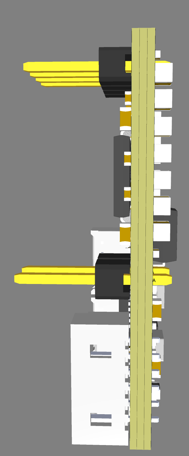
Here is a full stack driver board complete with all I/O and power management.
It’s really expensive, about $60 to manufacture. I’m not sure people would be interested due to the complexity and cost of the board since it’s double-sided.
The upside is that it’s fully integrated and really tiny, 20 x 30mm and got SPI, I2C, UART and SWD connectors. Using STM32F103 which is a very mature MCU.
Well, one day if I really have time I may fab it and test it out.
I’m curious if you have any plans to share the schematic for this board. I’m looking to implement the DRV8412 into my stepper motor project and it would be extremely helpful to have and would be extremely appreciated. Thank you
Wow, thank you! I assumed there was no way that LCSC would have it, much less have one in stock, so I didn’t even check. This will make it much easier to make via JLCPCB. Thank you!
My concern with the double sided board is that it may not dissipate heat very well. I haven’t used this driver yet, but if running it anywhere close to 5-6A I would imagine it would get incredibly hot. Luckily, my application has a lot of room so I will make sure to use massive ground planes on both sides, and maybe use 2oz copper instead of the usual 1oz. Have you had issues with your smaller test board?
Hey @Valentine, is the reason for so many ceramic caps because you are trying to avoid electrolytic caps? I understand the downsides of electrolytic caps, but just curious why you didn’t use a large one here?
Because electrolytic are large, expensive, high esr and low lifetime. Ceramics are practically indestructible, low esr, low inductance, cheap, basic, non-polar, excellent high frequency response, non-temperature dependent. Also they don’t explode in your face when over-stressed.
@Valentine, I just wanted to share what I learned about the downside of using all ceramic caps for bulk capacitance. There are ways to avoid this, the simplest is to not plug in the wall adapter until after the connection to the PCB is made. This is an interesting in-depth read on it: