Trycycle brushed, brushless, stepper auto sync example

SimpleFOC came up in a discussion about a motorized autonomous tricycle and we thought it might make an interesting example project to demonstrate use of brushed, brushless, and stepper motors all in the same project and syncronizing their movement automagically with a bare minimum of user input. Its just a napkin sketch currently. Seems possible.
Would like feedback whether you think this would be useful as an open source educational demonstrator prior to investing more time in it.

2 Brushed wheel motors in a symmetric differential drive configuration without encoders.
1 Brushless wheel with hall effect encoder.
1 Stepper with incremental encoder controlling the steering angle of the brushless wheel.

The brushless wheel may be in front or behind the brushed axle and you do not need to tell the software. Encoder count and direction does not need to be specified, it just needs to change in proportion to steering angle controlled by stepper. Wheel diameters and other build dimensions do not matter. Attach any hardware conforming to the above lines, set it on open level ground and it will do a self calibration and just work.

The goal is to write software controlling multiple SimpleFOC modules which will sense what type of motor and encoder is plugged into each port. Brushed motor ports will be open circuit on exactly 1 phase. Stepper port will be the only one with an incremental encoder. Brushless will have all 3 phase connections. The auto configuration can attempt motion on various ports and look for encoder and current feedback to determine which is which.

At first, the brushless wheel and steering axis are undriven and their sensors merely observed while brushed wheels are driven.

Once ports are sorted, apply equal low voltage to both brushed motors until steering encoder settles into a stable value or a stable oscillation. Stop. This direction will be assigned as Forward and can be toggled by user. Because the brushed wheels are coupled to the brushless through the ground, watching the hall commutation sensor rate while driving straight establishes a relationship between brushed Kv and brushless commutation rate.

Apply opposite, same low voltages to each brushed motor until steering encoder settles into a stable value or a stable oscillation. This direction will be assigned as full left spin. Note the number of encoder transitions and encoder direction from “Forward” state to “full Left spin” state.

Repeat for Backward and full Right spin. The difference in number of encoder transitions between Left and Right spin is an indicator of steering axis offset from the differential drive axle centerline. This is a low precision value that can be improved with more driving, but it sets a rough upper limit on full lock to lock steering counts ~>180 degrees.

That is enough for basic calibration while consuming a minimum of floor space. With a longer straightaway we can explore how changing differential voltages affects steering angle over time and how steering angle actuation by stepper affects encoder direction and rate as well as differential brushed current.

It is unclear whether we will be able to achieve straight line driving and turn negotiation with this most basic sensor suite, but we have some things to try.

After calibration, basic teleoperation could be done by sending characters.
‘E’ ‘e’ or ‘space’ Emergency Stop
‘F’ ‘f’ ‘up arrow’ or ‘W’ ‘w’ Forward
‘L’ ‘l’ ‘left arrow’ or ‘A’ ‘a’ Left
‘R’ ‘r’ ‘right arrow’ or ‘D’ ‘d’ Right
‘B’ ‘b’ ‘down arrow’ or ‘S’ ‘s’ Backward
‘tab’ Toggle the direction defined as Forward
‘+’ increment keystroke multiplier *10
‘-’ decrement keystroke multiplier *10
Any single number preceding a valid command multiplies the effect of a single keystroke.
1 turn keystroke = 1 steering encoder tick.
1 direction keystroke = 1 brushless commutation.
2 numbers preceeding a valid command; first is the number of keystrokes, second is the rate of keystroke repeat. 100 is the normal repeat rate.

To my knowledge SimpleFOC doesn’t control brushed motors. You will need something completely different for that. Brushless and stepper would be no problem.

If I were you I would go for 4 onmidirectional brushless wheels. Tricycle is very restrictive. There are very well known algorithms doing what you want, for a 4-wheeled omnidirectional platform. I’ve implemented one myself, but instead of all those commands you listed I just hacked a PS4 controller and steered it with the joysticks.

Cheers,
Valentine

I’ve built omni robots and taught how to do that, but that isn’t the goal here. This project would showcase the versatility possible with a single type of hardware controller and no code (from the users perspective). A kid could pick motors from a pile of vastly different hardware and have a working robot in an hour. Tear it down and the next class can do the same. All the bots looking much different, but working basically the same. To make it easy to give students a taste of success with little guidance. The basic text based interface allows operation from any computer, microcontroller, even just by plugging in a keyboard or switch based joystick. Which would be an intro to the next lesson.

Hi @slomobile ,

This is certainly an interesting idea, and sounds possible in principle…

An added complication you’ve omitted in your otherwise very detailed description is that the motor phase wires aren’t really standardised for any kind of motor. The DC motors often have a red and black lead, but that’s by no means required. Leads could have many kinds of plugs or bullet lugs connected to them.

So when you describe a “port”, its not completely clear to me what this would look like. But unless you can figure out a way to ensure motors get connected with a known “direction” to their phase leads, there is an added step in the calibration where you have to figure out the natural direction of each motor for the way it is connected. For the stepper with its encoder this is easier, but for the others it is actually not so simple to do it without further user input, I think.

I also wonder about the benefit of the “port sensing” since you know in advance which motors you expect, why not make dedicated ports for the different motor/encoder types? I think this may actually be easier for the user than having 4 ports each with 9 lines, some of which get used and some don’t.

Also in that context, what is the driver architecture? I take it you intend to have the motor drivers for all 4 motors on this PCB. I think that with a powerful MCU with enough pins, it would be possible to control 4 motors where 1 is BLDC, 1 is Stepper and 2 are DC.
But they have quite different driver architectures - a DC motor needs a single half-bridge, while a BLDC needs 3 half-bridges, and for a stepper it is 4.
So I guess you could make “ports” with 4 half-bridges on each, and 5 digital lines (Hall A/Enc A, Hall B/Enc B, Hall C/Enc I, +5V, GND) each, so that any port could take any motor. But it would be fairly wasteful as 7 of the 16 half-bridges would not be used.

It would also be a big challenge in terms of pin assignments and timers. Lets assume the bridges are each controlled by a single PWM signal (e.g. having internal dead-time insertion and shoot-through protection in the FET driver) as opposed to 2 PWMs per bridge. So that would mean 3-PWM control for BLDCs and 4-PWM for steppers.
So you’d have to find a MCU with 4 timers each of which has 4 PWM channels for use - I can tell you right now that this will limit you to a few STM32 MCUs in terms of what you can use to do this. Or you design a board with multiple MCUs on it - which will be super-complex to bootstrap and update.

So basically I would urge you strongly to make dedicated ports: one for stepper, with 4PWM, one for BLDC, with 3PWM, and 2 for DC motors, with only 1 PWM, each with only the FETs and drivers needed for the task.

Teensy is my usual goto board, but ST or ESP32 are fine as well. The entire project would require 3 identical boards. Each containing a microcontroller and drivers. After doing this project to learn how motor types are different and the same, the hope is that they will pick up one of these modules and an appropriate motor whenever they want to quickly test an idea in the future.

My thought was a modular board with 6 half bridges, 6 PWM, encoder AB and Index on the same pins as Hall ABC with +5 and GND as you mentioned. SCL SDA and GND for interboard coms. Battery power and ground. So 16 terminals on each board. Leftover GPIO routed to pads for selecting I2C address, LEDs and external coms.

Whichever board finds itself connected to the DC motors takes the role of coordinator because it has no encoders to watch and it runs open loop. I hadn’t given much thought yet to the general case of selecting a coordinator. Maybe lowest I2C address is coordinator. Or connect to USB Host and write a configuration to EEPROM to select other than the default config.

The purpose is demonstrating modularity. With just 1 board design, each is capable of running either 1 BLDC, 2 DC motors, or 1 stepper. It only discovers its role at runtime.

Wiring and finding motor direction is part of what is taught. If the first test doesn’t drive forward or backward, they need to hit E stop and rewire. Dead simple, “unable to do it wrong” plugs do not present the same learning opportunity.

@slomobile

That’s extremely challenging. I will watch this and hopefully learn.

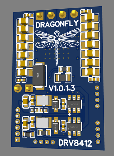
I designed a generic board like that, but it came out really expensive. This is the board:

If you are interested, I could open the design. Check out this thread.

Question, do you have anything to do with SLO Cal Poly? Or slomobile is just something else?

Cheers,
Valentine

1 Like

I’d buy a couple of that board to evaluate if it can handle 56v. Data sheet says 52v recommended for the chip. If you are willing to open source it, that would be great, I’d definitely check it out. Your call. Thanks for doing that.

Making it easy enough to build in an hour is mostly down to premounting the motors to modular building systems like Actobotix, Tetrix, Vex, 80/20. Thunderhex shaft and bearings.
PVC planks and project boxes instead of wood. Reworking PVC conduit with a heatgun. Harbor Freight all in one drill/taps. Aluminum profile. Minimizing different screw sizes and only 1 type of screw head.

Slomobile is a '62 Pontiac Starchief that I Frankensteined many projects into and eventually became a nickname.

It cannot because some of the components i used are only 40v max. I need to redesign it for 56v. The chip itself will handle up to 70v.

The board would be expensive, about $100 a piece. Im not selling for profit, thats at cost, not counting shipment and tax/ import fees if you are outside USA.

Let me know.

Cheers,
Valentine

Ah, ok, so then there are multiple driver boards - this makes more sense.

Why 6 half-bridges? For the stepper you need 4, and the BLDC you need only 3. For the DC motors, 4 half-bridges can drive 2 motors for both speed and direction.
6-PWM is supported only for BLDCs, when controlling the FETs individually. But this isn’t supported for steppers (which would need 8-PWM in this case).

Probably you want 2 I2C ports to be able to connect the 3 boards without needing an additional hub? “Stemma/QT” and “Grove” are two kind of standardised plugs for I2C connections.

I guess one of the largest challenges will be the power stage and motor selection. My “grab bag” of motors under $20 includes some pretty different types. Id say the range spans 47KV to 18000KV and the voltages go from 1.2V to 30V on the BLDCs.
The requirement to support the different motor types means you most likely can’t use a dedicated motor driver IC with built-in protections. Maybe you can find a single half-bridge IC with shoot-through and over-current protection, that would help a lot.
Otherwise you’ll be building the half bridges most likely from simple drivers and N-FETs, and if you don’t design in some protections, the risk of burning something will be quite high when connecting random motors…

Sorry I neglected to make that clear in the first post. Your questions point to another half considered idea I failed to mention.

6 half bridges, 6 PWM, 6 phase wire connections. Some reasons.
Run a motor with isolated phases, or alternators as motors (3 phases plus PWM field coil).
2 sensorless BLDC as differential drive with a steering encoder for a powered caster.
Motor amp. Inevitably someone will want to drive a motor with volt/amp requirements higher than the base module. Rather than have several base modules, have a few add on high voltage/current push/pull bridge modules using the base module as a driver. Efficient, brief shoot through protection built in to the base module will be too short for the larger motors. Timing each half phase individually allows customization to the hardware actually used. These “motor amplifiers” can also have I2C EEPROM onboard to store and transmit motor amplifier capabilities and configurations.

Yes, daisy chain I2C ports. I was thinking long through hole Dupont pins and connect to both sides of the board. With the board intended to be vertical so it can have heat sink on both sides and mounting to structure accomplished through heat sink fins. But if Grove or other is truly ubiquitous, it might be a better choice.

The amplifiers and traction battery could even be mounted at the wheel motors for infinite caster rotation with only the low current phase driver wires routed through a slip ring.
I’m sure there are other uses, I just didn’t want to arbitrarilly limit the use cases just because I hadn’t thought of them. This is not aimed at lowest possible BOM, but at highest possible utility for rapid design iteration. It is for education and producing proofs of concepts. Juggle generic on hand components till it barely works, then generate a proper BOM for building a prototype.

It certainly sounds like you have a concept and I look forward to seeing the results!!