Hello everyone,
Thank you very much for all the work to develop the SimpleFOC library.
I’m currently designing a power shield to work with a Bluepill board (STM32F103C8).
My main goal is to create a board with available components from JLCPCB, easily replaceable if one goes out of stock. I planned to use it with an 18S battery (max 80V) to run a big ebike motor with 35A max current phase.
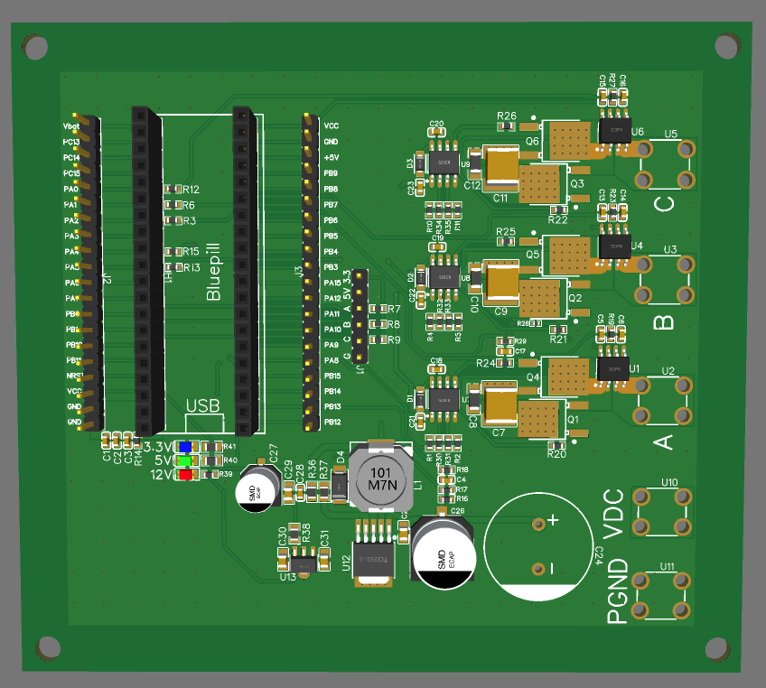
I’ve started by making this schematic :
My only comment would be to watch out for this driver. I could not make it work. May be you will have better luck than me. I did make the integrated three-phase Sillumin driver work, however, you may want to experiment a little. Also, these types of drivers are hard to test standalone, they require mosfets connected to them to work, so watch out. Best if you use Infineon drivers?
If you have not designed a power stage before, please post your layout, we may be able to provide some feedback.
To be honest, I already made a driver with these Gate Drivers (EG2132) and I’ve never been able to make it work correctly and smoothly, but I didn’t know if it came from the drivers or somewhere else.
My main goal is to use affordable gate drivers that are in stock. I will check Sillumin and Infineon. I used to use TI gate drivers which are very good but they are out of stock unfortunately.
Is Sillumin SLM7888 a good choice? Or 3 SLM2009, it looks like it has better performance and I don’t really have space constraint.
Thanks for your help. I have already designed some motor controllers before but I don’t have a lot of experience, I learnt by reading datasheet and watching others people design. I will share the layout when it will be finished. If it works well after testing, I will make it available.
One last question, which pins of the Bluepill are the best to use for the encoder/hall sensor?
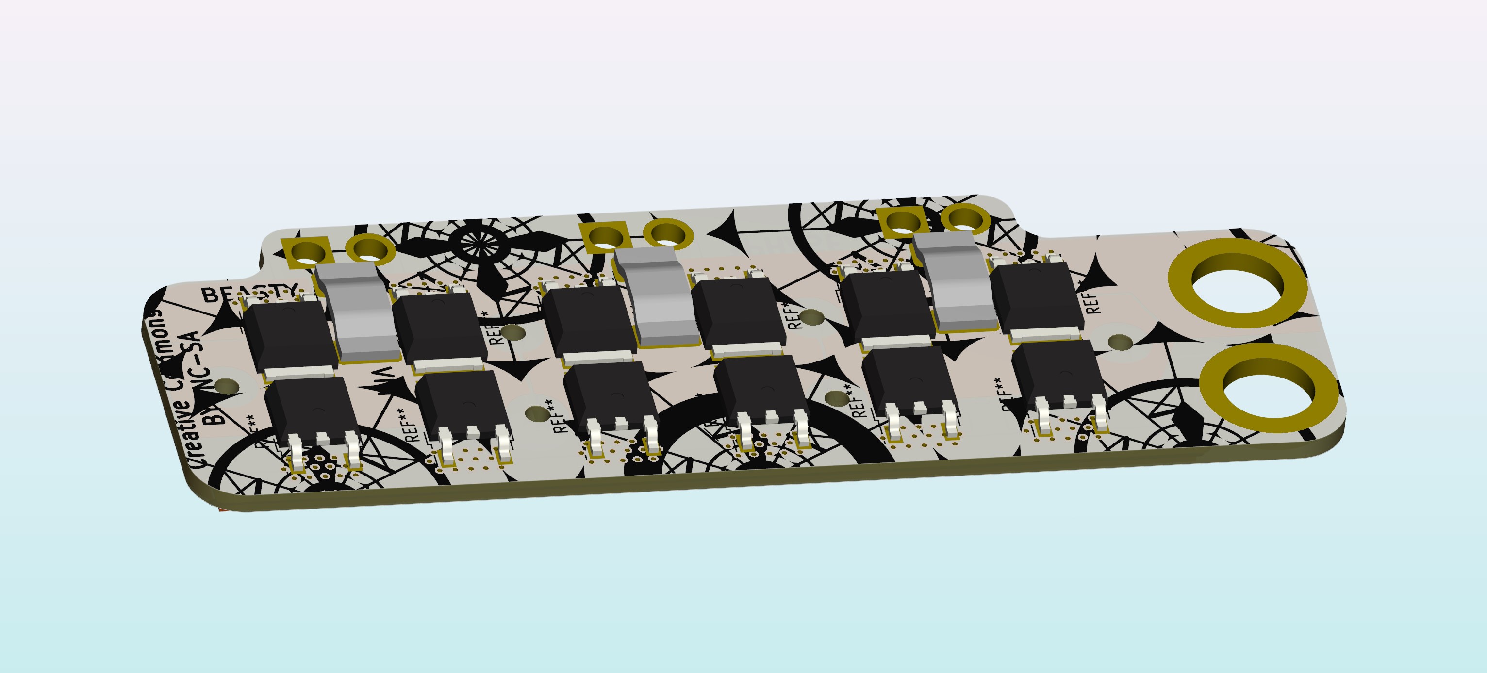
Check out how I’ve sketched this modular approach. It could be nice to have a universal modular power stage standard which can interface with various controller/MCUs. BLDC co troller stack. Depending on the mosfets it could reach 80v.
But let’s say you need lower rdsOn (resistance) aka faster switching and you could be content with 36v, then the modular approach lets one reuse the same MCU in a different Stack config.
Hello @Juan-Antonio_Soren_E , thanks for your answer. Your project is interesting, I also want to make something modular and I thought about using a bluepill board because currently, it’s cheaper than a single STM32F103 and it’s easily available. It also integrates all the peripherals to make the MCU work.
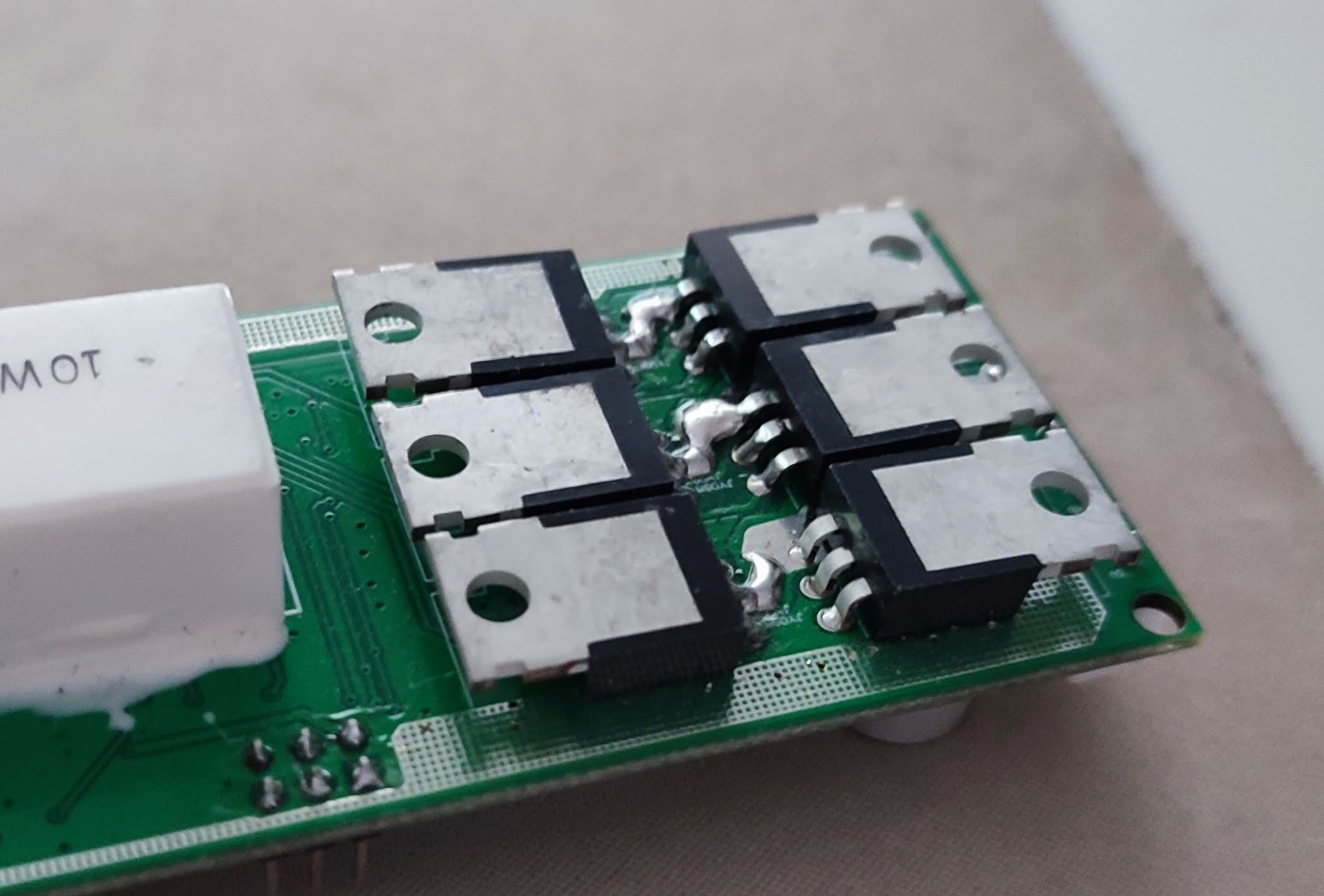
About the FET, I think I will choose low RdsOn and low Qg TO-220 FETs and put them like on the picture below :
I made this design for a water pump motor controller and it’s very convenient to mount it on a big heatsink.
If we want to go even further, we can stack the bluepill on a first board with the gate drivers and DC-DC converters and all these two boards will be stacked on a third board with the power components.
If the first sample works correctly, I will try to add a circuit for a braking resistor in case the system works on a power supply.
Thats interesting, although you will have to do the test to ensure temperatures are below your goal. Have you found the FETs?
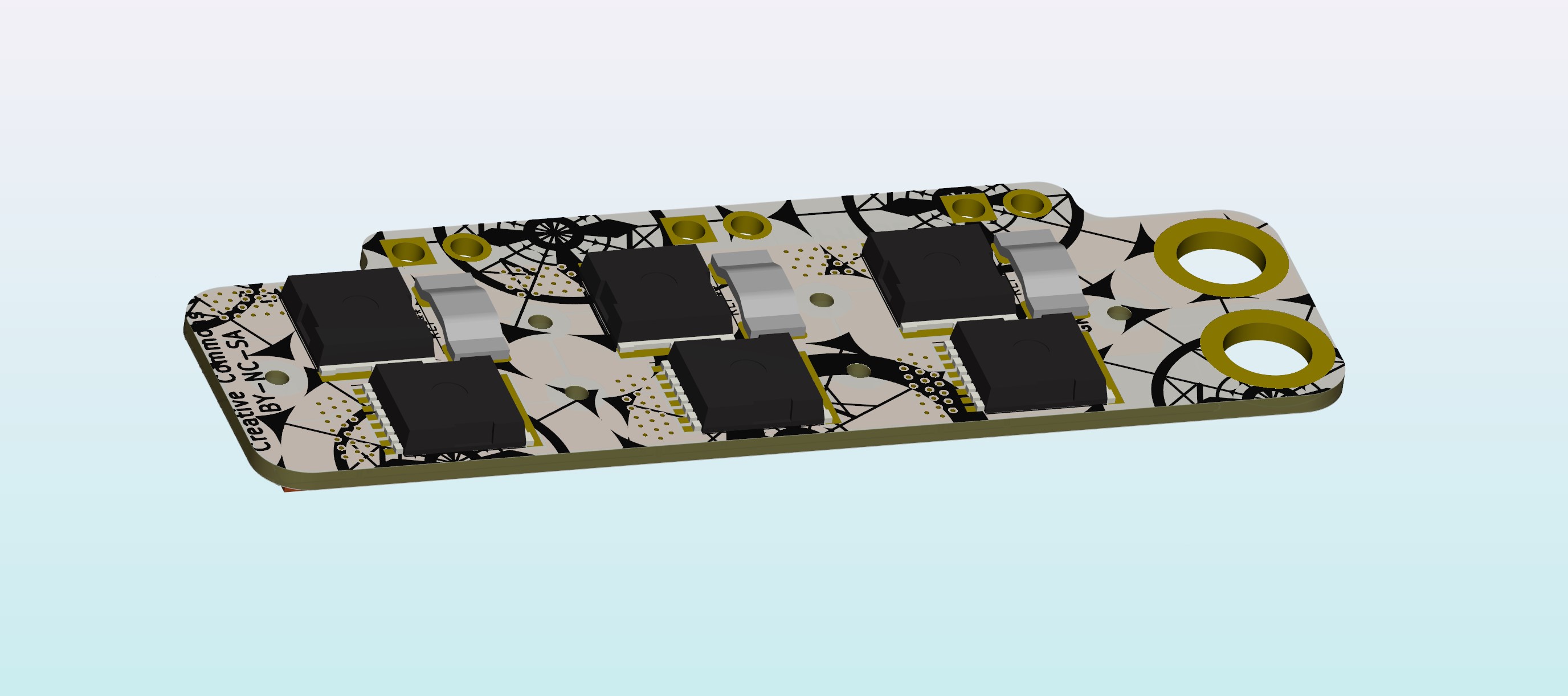
Yeb, modular power stage, you could in theory have dual FETs (4 TO-220) on each bridge and mount the heatsink to bottom side. It depends on how practical it is to integrate those footprint. I know @Valentine will not recommend dual FETs but that’s is a matter of opinion and quality of FETs, how evenly they switch. Or you could go larger.
EDIT: I guess in order to make a “standard” one has to name it and define it.
This is comparing TO-220 to TDSON-8 footprints. Those TO-220 are large, relatively.
Looking at what TO-220 i can find on mouser, the TDSON-8 footprint, even though much smaller, can carry significantly more current? What price point are we looking for and which on_resistance?
Since the end goal is a ebike motor controller, IMO it is neat to make it compact. You know stuff for bikes tend to be compact and as light as possible. Are you stuck on the TO-220 footprint?
Hello @Juan-Antonio_Soren_E ,
For the moment, I chose TO-252 FET. They are AllPower APG095N01K, 100V 60A 7.5mOhm RdsOn. I mostly choose them because there are a lot in stock on LCSC and it’s more convenient for me because I can order directly a full assembled board from JLCPCB. There’s also the constraint of one side assembly. I started the PCB design and for the moment, the board would be 104mm*91mm, which is acceptable for me.
If this board works well, I will try to improve it later with better FETs and make a more powerfull board. But for higher current, the next problem will be to find available and affordable current senses amplifier.
I made larger borders in order to screw it easily in a box. I might add an heatsink over the FETs and maybe a fan if it’s too hot.
What do you think?
Thanks
I see, yeah that does make it more challenging. But maybe with through hole and DIY solder Caps it could be possible to reflow one side and hand solder second side.
Hmm… to get 35amp out of it, you need to consider thermals. Like it’s always the case. If you go this big, then use the area to create a wide VDC track.
Will be interesting to see how those Hall effect current sensors work out. Are they in stock? Which part is it?
Since you have this large area, I would consider bigger FETs or maybe find a way to double the FET count.
Just want to point out one thing. Although the specs state 60 amp for those FETs it is really relatively. Relative to the switching freq. you wish to work with.
I will try to increase the VDC width and maybe expose the copper to add some solder tin.
I saw these transistors but their cost is quite high. I can double the FETs and use smaller ones.
For the moment, I was looking to make quickly a prototype to see if I can make a motor runs smoothly, even if it’s with lower power. And then, increase until it burns
Does your controller work well or you are developing it too?
I just right making something simillar.
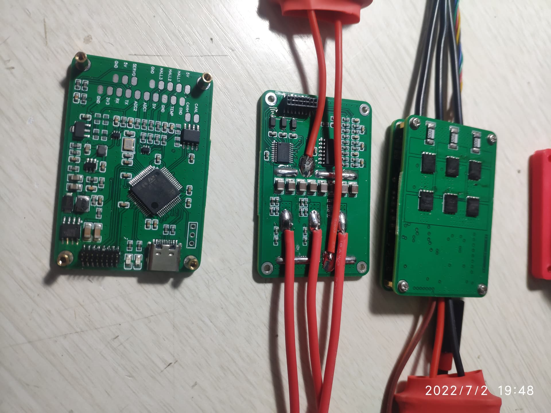
This is a VESC compatible focer without DRV8301 but FD6288. Named PingFocer, the size is 40x60mm. So far it’s tested under 50v and is capable of handle over 500W. Still I’m looking for a way to absorb more mechanical power so that higher limit I’m able to test.
Since it got build in low side current sensor and its based on STM32F405, I thought its easy to use with SimpleFOC. In a few days I’m gonna to release the full design to the com
munity after more test. Besides ,its “JLCSMT compatible”, everything is on one side except MOSFET and the sense resister.
Hi @Juan-Antonio_Soren_E
Sorry for my late reply, I got Covid few days ago and felt a little sleepy
When I started this project, I mostly wanted to use available and affordable components so I can make a prototype without spending too much money. I’m totally new to SimpleFoc and I started this project mostly to learn and use it with the big motors I have in stock. I’m not that experienced, but I’ll be glad to help you in your project. How far are you in your project progress? You work on KiCad?
About the FETs footprint, in my point of view, the best would be to use the most standard one so it’s easily replaceable.
It seems JLCPCB also offers double side mounted now, so it’s not a problem anymore! I’m located in France but I have a reflow station too but if everything can arrive mounted and ready to use, it’s more convenient Thanks for the offer. I used to assemble the PCB by myself before but then I found SMT service on the internet
Looks great! Mostly if there’s no DRV8301. Do all VESC are hardware compatible with SimpleFoc? Because I have one in stock so it would be quicker for me to test SimpleFoc with a “higher power” motor.