Just ordered the Portenta H7 Light, so you can say i will start from scratch. Do have some prior experience with SimpleFoc using the SAME51 120mhz MCU. With this modular approach, I might try the SAME51 again at some point, to see how it compares to the STM32H7. The cool thing about the modular power_stage, is the ability to test and compare different MCU´s on the same hardware. There is also a sustainable aspect to it, since it allows for better reuse of the MOSFET´s or the MCU etc. in different configurations.
It seems JLCPCB also offers double side mounted now, so it’s not a problem anymore!
Wicket! Thats nice.
I will create a repo, defining the “standard” (dimensions and header placements) for the proposed design. Naturally the goal is, to introduce various “variants” with different specs. Like stated before, one can then mix and match with different stack configurations. Ultimately, making a more compact design, doing components on both sides, should bring down the cost. But there is also some design choices, which should optimize the overall design, like cooling etc. If you wish to dive into the Bluepill, then why not, but maybe you want to compare the Bluepill to the Blackpill or some other MCU. The Teensy 4.0 maybe. Maybe Teensy 5.0 when it eventually arrives. Doing the modular power stage, you dont “lock” the FET´s to a certain PCB, like the one you posted earlier. Its like a proof of concept.
@hbozyq
Those FD6288 looks interesting, they are definitely quite affordable. Great work on the PCB! Its really cool to se hardware in the making. Do you plan to put a heatsink on the FET´s? How are they holding up heat wize and what part is the FET´s? Looks like you have lots of space to expand the power stage…
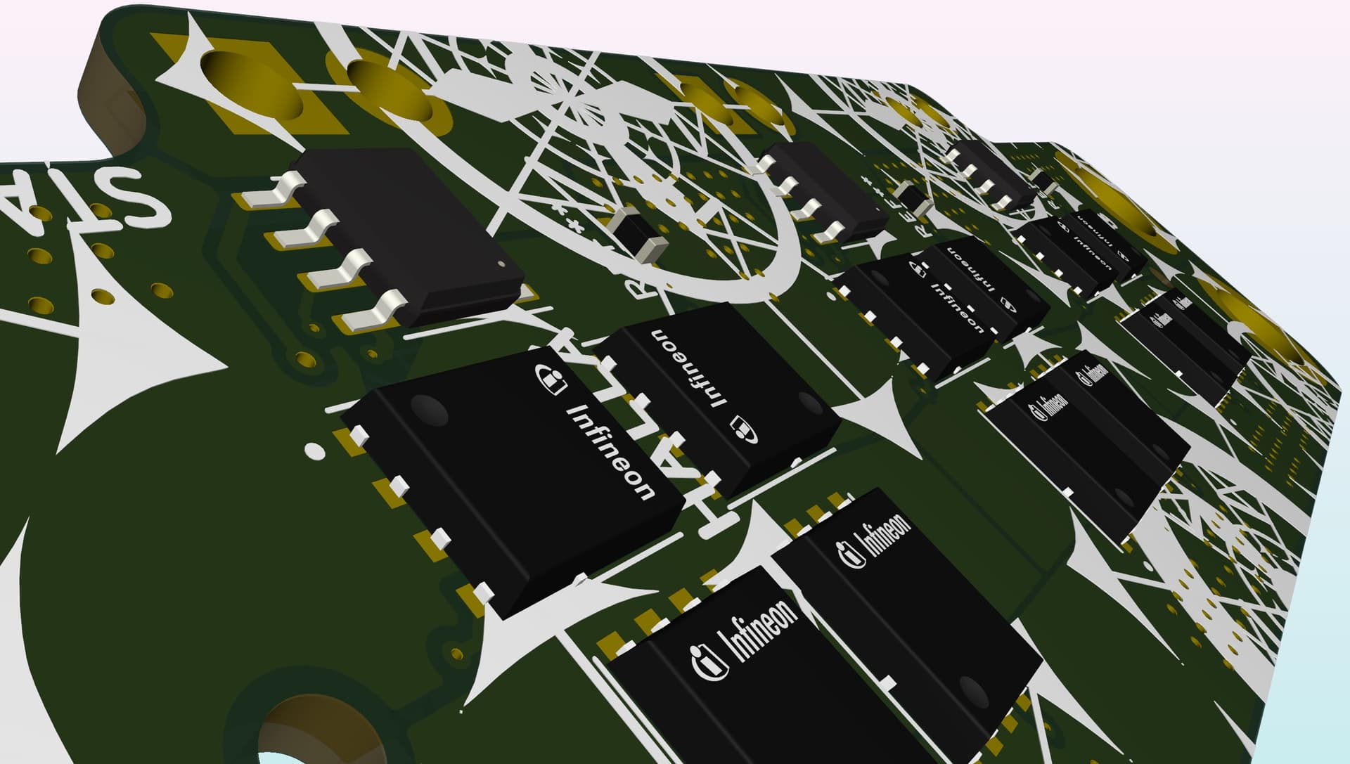
For now I’m using CSD18540Q5B. I got 4 layer and lots ground copper around the FETs so the PCB itself works as heatsink. With less than 2mOhm RDS its capable of 25A continue current painlessly without external heatsink. It would be easy if additional heatsink is required.
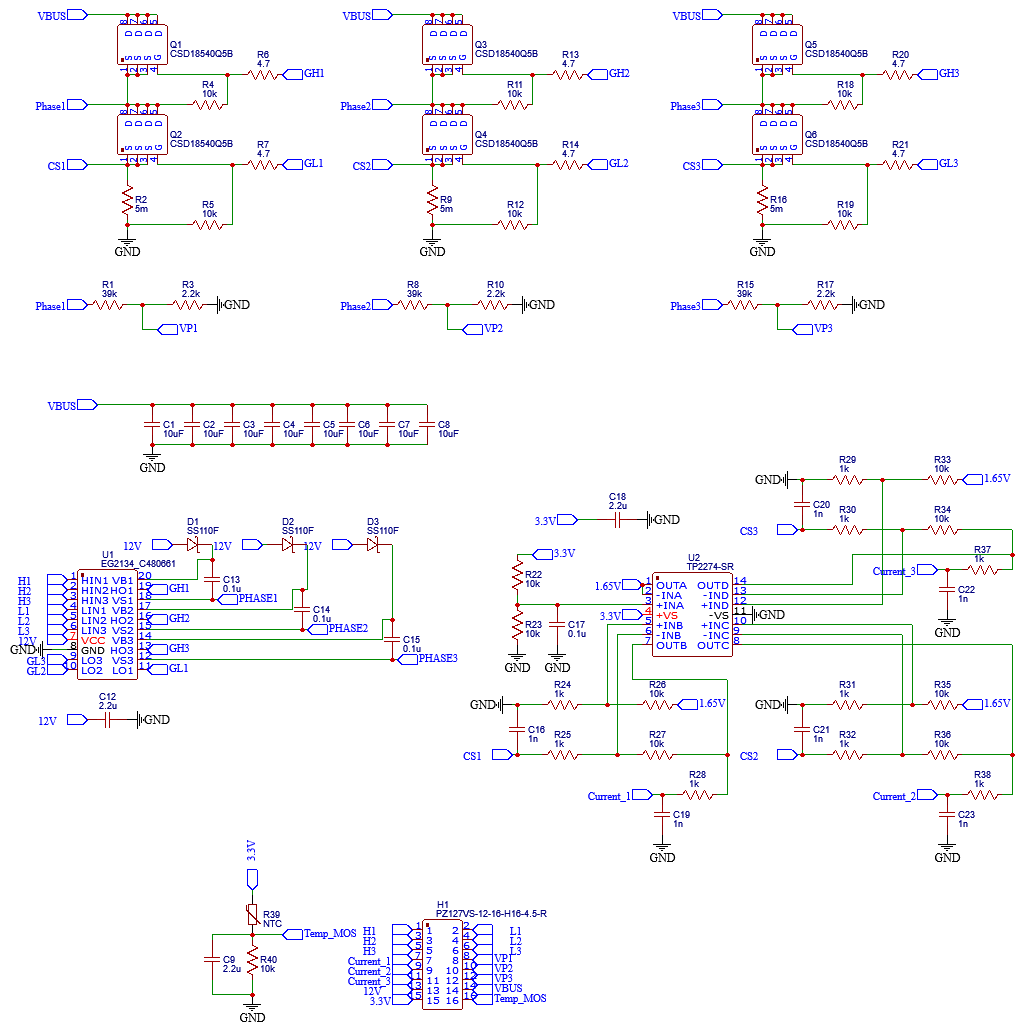
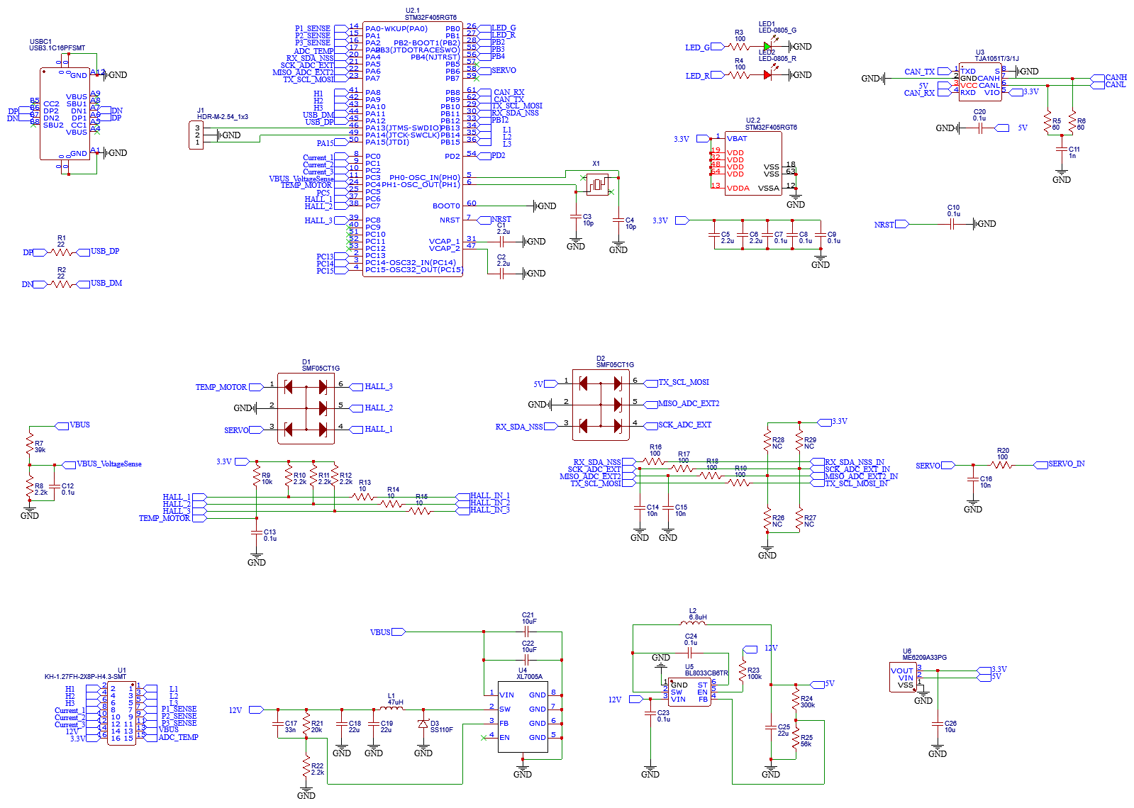
And heres my schematic. Just for preview. The power stage and MCU is on two seperated part so its convenience to modify to meet your own need.
I see, they look pretty sweet for a 24v to 36v system. Lots in stock and a decent price. In my experience, it is a challenge to increase the voltage to say eg. 14 Cell Lithium (52v’ish) since the whole system has to accommodate those higher voltages. Like the OP says, he aims at 80v, 18 Cell, which really pushes those 100v FET´s. I remember those early VESC´s having some issues burning up at higher voltages. I guess they learned the hard way. Im really exited about the TI INA241A current censor, still in preview, with none in stock at this point. Lets hope no billionaire buys up the entire global stock, just to become even more rich, when it arrives. Unfortunately TI declined my inquiries for samples to develop with the INA241.
There is also the option to extend lower voltage rated current amplifier voltage rating or maybe increase pwm rejection by external components. Could be a viable route forward.
Do you or someone else have experience with these. (@Valentine )
From the specs they do look quite promising, but maybe 35 amp is pushing it, on two SOP-8 legs. This is where the specific need´s of a ebike controller comes into play. In EU the legislation says 750w is MAX for ebikes. Not just normal ebikes (where the limit is 250w) but those larger ones with some specific rules.
I dont want to discourage you or anyone, actually from the viewpoint of the SOP-8 sensor, it is a good thing. It just means being really specific when it comes to how the overall system is put together. Especially the motor windings with relation to the current sensing. So if 750w. is the top, @80v that is below 10 amps. In that case, I will say the CC6920BSO-20A is more suitable and also more realistic when it comes to current draw through those small legs.
@TimothEe02 When you say bike, are you talking street bike MC or a partly human/pedal driven ebike?
I think when it comes to pedel-bikes we have to be very specific with regards to the actual setup, in order to get the most torque out of those 750 Watt. Considering range is not a bad thing, it just makes it challenging, and it ultimately may lead to rewinding the stator. Rewinding may sound annoyingly cumbersome, but why should your motor winding dictate the entire system ? Knowing the exact motor you have would help ?
When I talked about 35A, it’s 35A peak, phase current. I don’t expect to go far over 1200W peak power (high torque at low speed or low torque at high speed)
The motor I use is derived from an ebike motor, with a custom winding. It’s made to reach 450rpm with a 48V power supply. The other motor is a 1800W 60V HUB motor for electric scooter. I think it’s not the specifications I asked because I wanted it to rotate at around 1400rpm no load speed at 60V but the no load speed is around 2000rpm. So I have to provide more current to get enough torque.
But my first goal is to have something that work, to test SimpleFoc, even if I only have 20A max.
To be honest, I first wanted to use a shunt resistor and a current sense amplifier but the only suitable one I found was the INA240 and it’s out of stock everywhere or at a crazy price (I saw one at more than 40 USD!) Maybe I can design a current sense amplifier from a common AOP and some components around.
The INA240-SEP is in stock at TI, but its like 230$ per peace, i fist thought it was a joke.
Anyways, what you seek may be realized with the MAX40056F. It is possible to extend the voltage rating of 70V by using Zener´s and resistors. But 18 cell may be pushing that solution. Im working on 14 cell and do think it can be done with the MAX40056F. It has advanced PMW rejection.
Still the CC6920BSO-20A may be a viable solution. Its worth a try!
Coming back to the proposed modular approach, using the WFL-8 sensor, I think we can make a “standard” which has the ability to either be shunt or hall-effect current sensored, if the sensor is integrated into the power stage. This was not my first thought to do, but since the land is like it is, i believe it to be a good solution.
The 50v/v amplifier may provide 35-50amp… But again we are back to the sensed resolution of the specific need for a ebike. Settling on a shunt value would be a good thing IMO.
No, having either shunt / amplifier or Hall effect, but having the analog output on the same pin. That way the MCU/driver/stepdown layer can be used with both technologies, both having its own advantages.
I will sketch it up and show what i mean…
Edit: I see the INA241A has a neat (small) footprint. It should be possible to use that for future upgrades, when/if it lands. Keep in mind it is 1Mhz, so not all standard ADC’s can handle it.
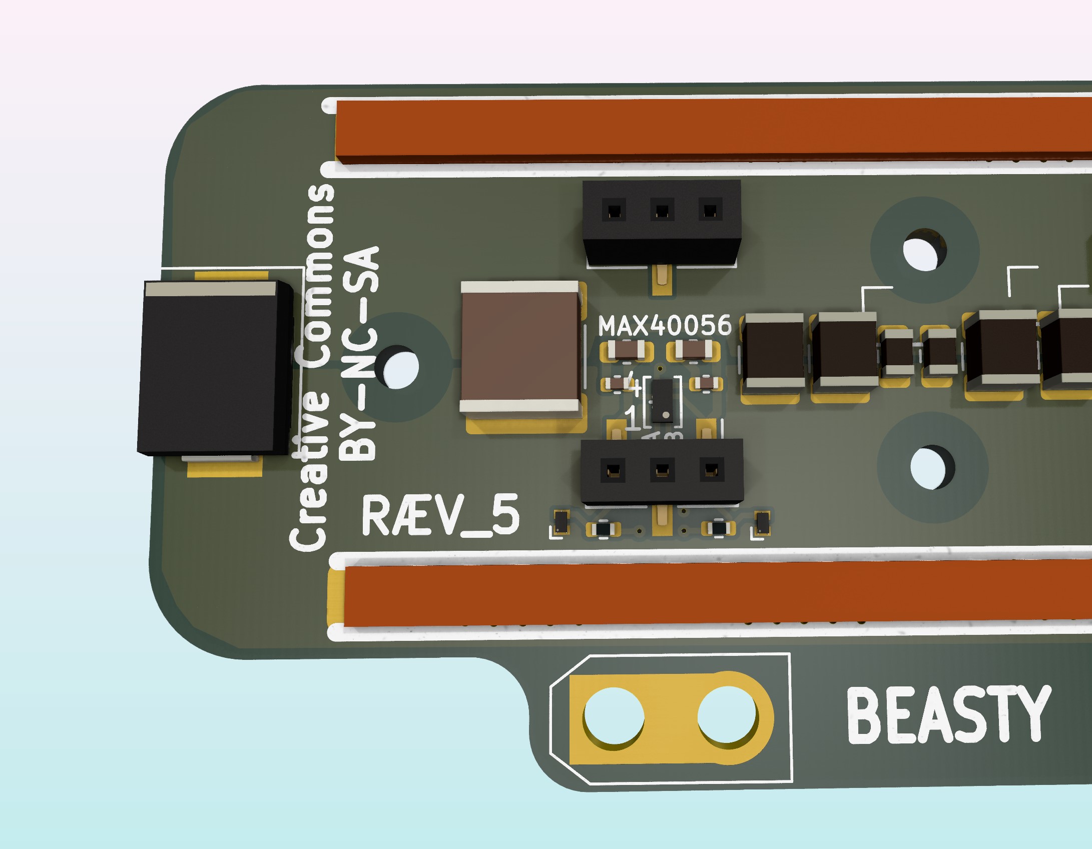
Here is a draft of how I imagine the MAX40056 WFL-8 footprint could be implemented into the power_stage. The GND for MAX40056 is digital_GND through the 2mm header pin. The Zeners drain the sense traces (transients) to switching_GND. Im not 100% curtain on the transient protection circuit, so will have to swing it by MAXIM.
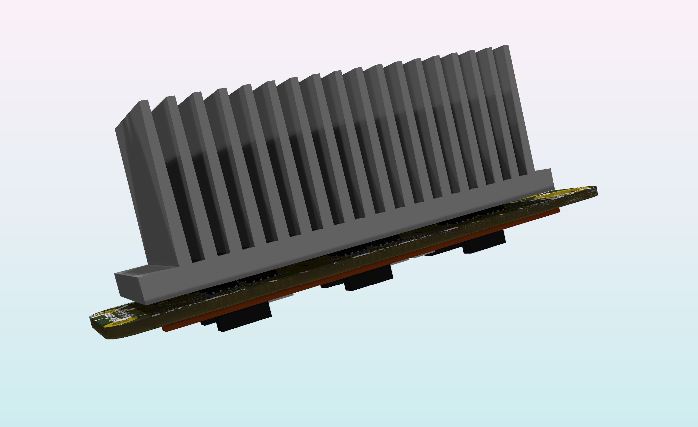
Here is the CC6920 Hall_Current sensor, instead of the shunt resistor. Sensor GND is digital_GND. The height of the part is somewhat a challenge if using the PowerFLAT 5x6 FET´s, since we have to make room in the heatsink. Some shunt´s are lower then those FET´s, but just a few. I have some 80mm x 40mm heatsink profile, which should fit.
The upside of having all the heat dissipating parts on the button side, is the possibility to bond the cavities with heat conducting silicone (not electrically conducting). That way, not only will the surface of the FET´s and sensor, transfer heat to the heatsink, but so will the copper pour.
Those are very different prerequisite.
So, as I understand it, your reason for aiming at 18cell’s is the scooter motor?
Using 80v on the scooter motor will bring up to around 2400w @30 amp rating. How much torque do you expect from it?
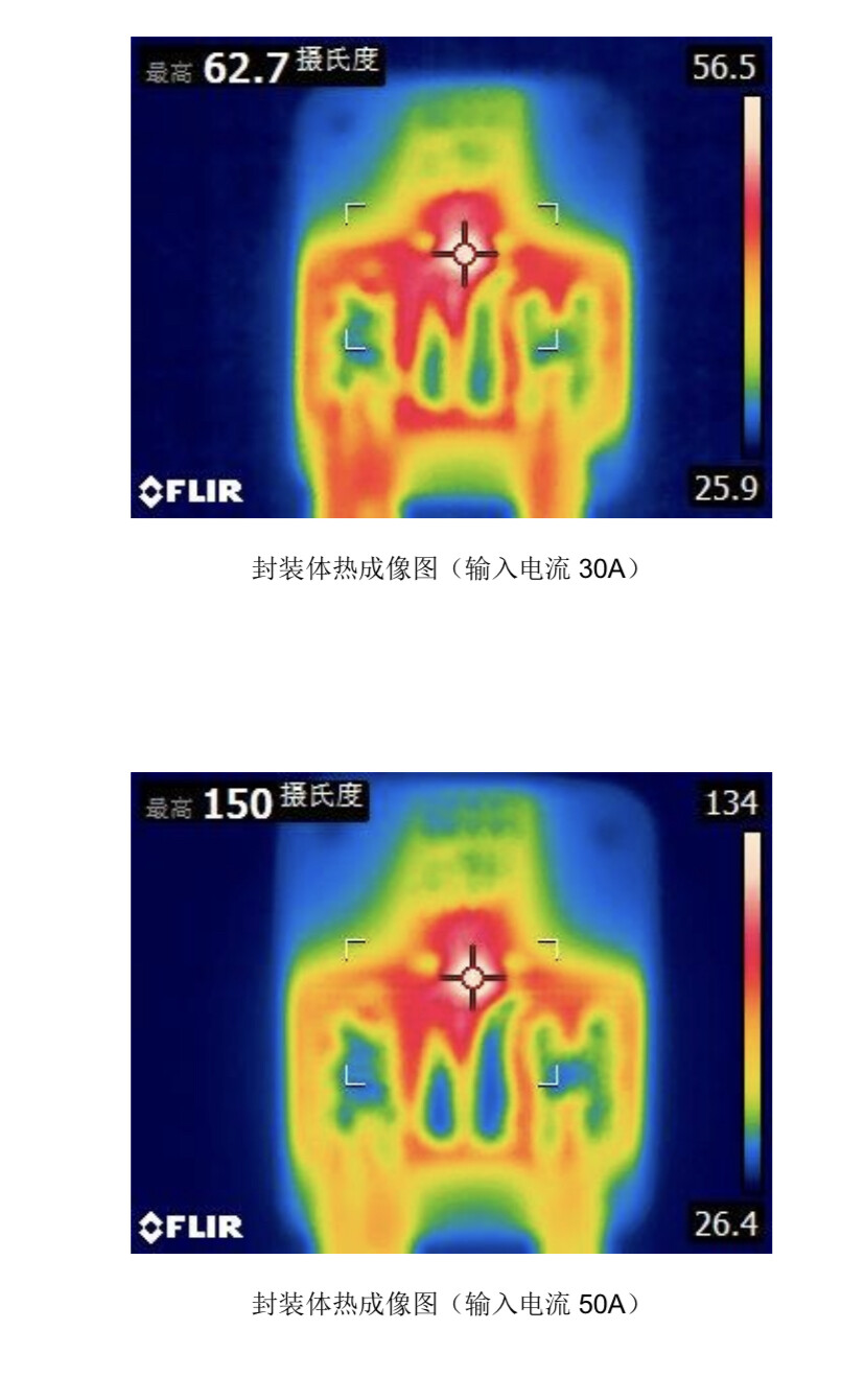
Just want to point out, having pedals and trying to stay within the 750w legal limit is a totally different scenario. None the less the above should handle 30amp @80v using the hall approach. With some 50amp bursts, maybe.
According to the dataset this is the difference between 30 and 50 amp:
Yes, the biggest problem is the Scooter motor.
Or I just design a controller for the 13S (48V) motor and I will see later for the 18S motor.
I already use an Odrive to control the 48V motor, it worked well. Maybe I can use the Odrive hardware and use SimpleFoc software to give a try.
The application with the 48V motor needs less power, less than 1000W. But it can get up to 50A motor current phase at low speed.
If you already have the ODrive, It would be pretty cool to have it run SimpleFoc, but I thought it already have a nice software?
Anyway, regarding your 18cell 80v desire. There is one thing we did not discuss. If you want a TVS diode to clamp those transients, then 100v FET´s is too low. You will most likely have to go for 150v FETs in order to guarantee, that the spikes wont harm them.
Like I stated earlier, I hope we can collaborate on the modular approach. If you would like the power_stage im proposing, with a “standard” MCU/controller interface. I can send one to France and with the heatsink. You can then focus on the Bluepill, Stepdown and driver integration?
It works very well but the software is too difficult to modify for me. I’m not good enough to modify and add new functions to deals with all the GPIOs for example. Like using GPIO to turn ON/OFF some relays. And it just become Closed Source.
I know, I know. Let´s hope SimpleFoc keeps its current trajectory. I think it will outperform both the VESC and the ODrive, once we fully harness the STM32H747 dual core potential.
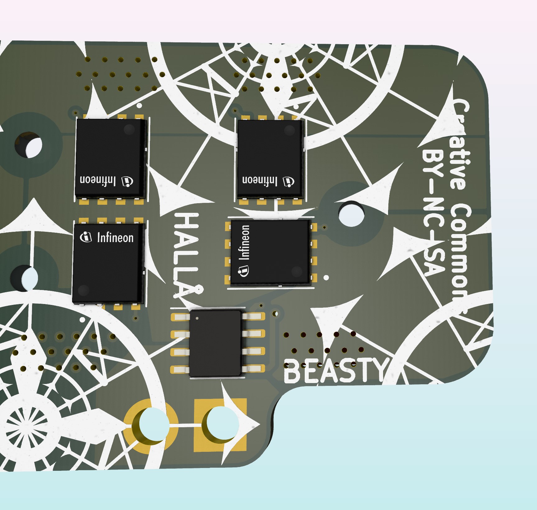
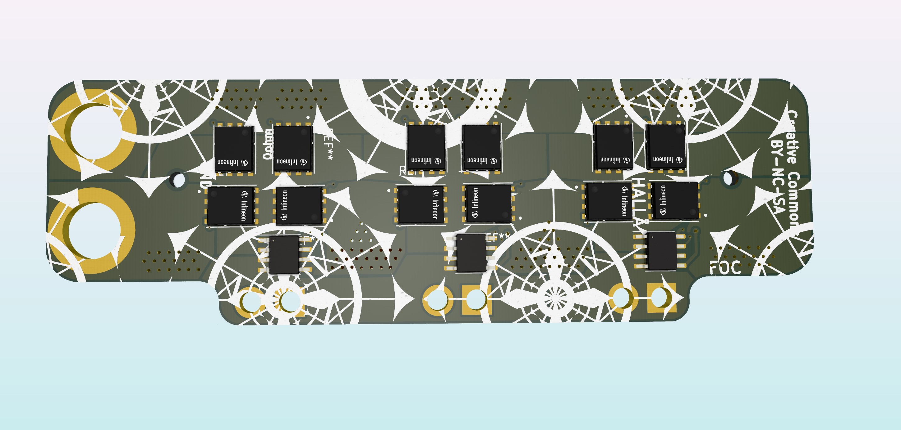
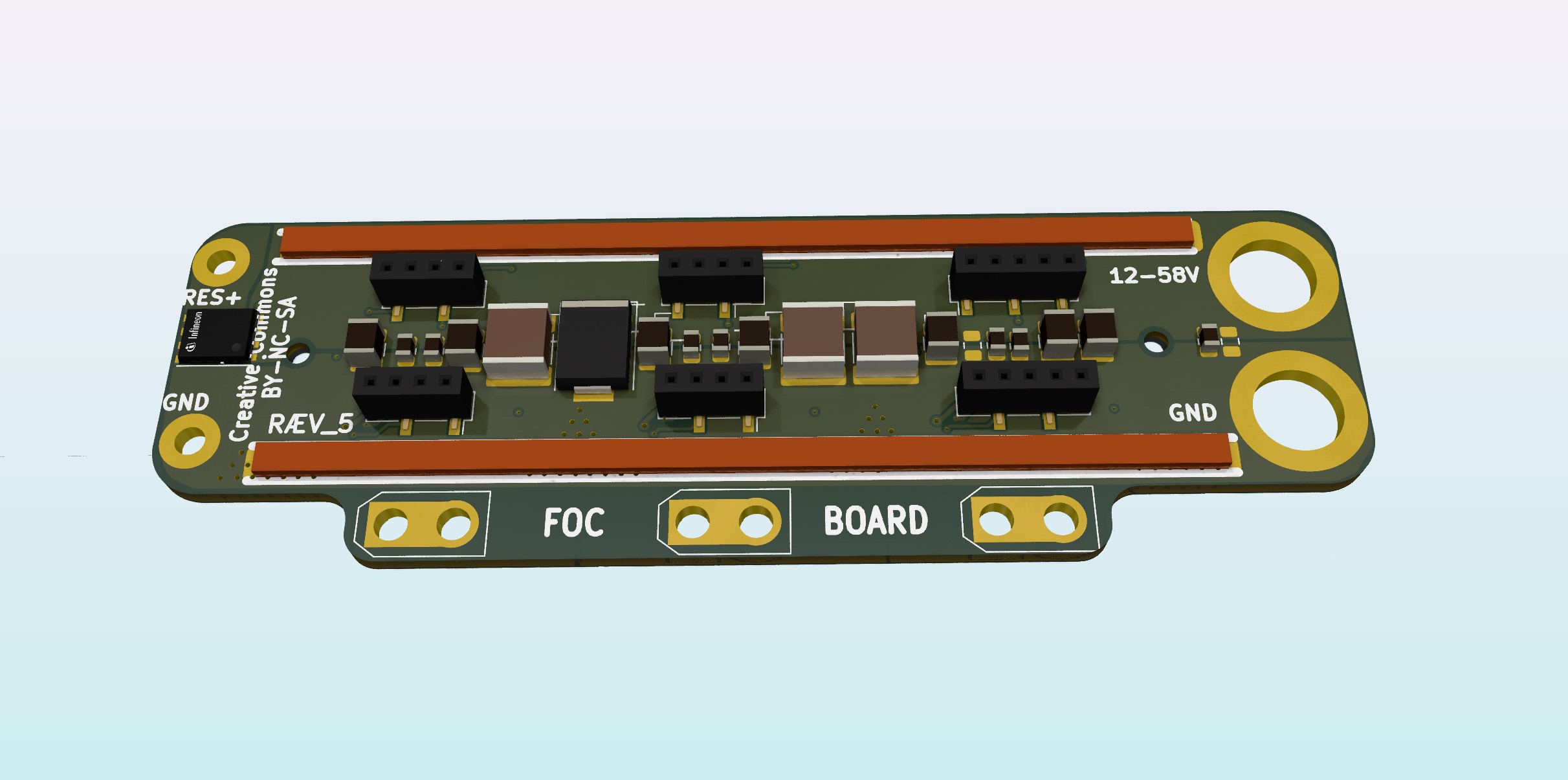
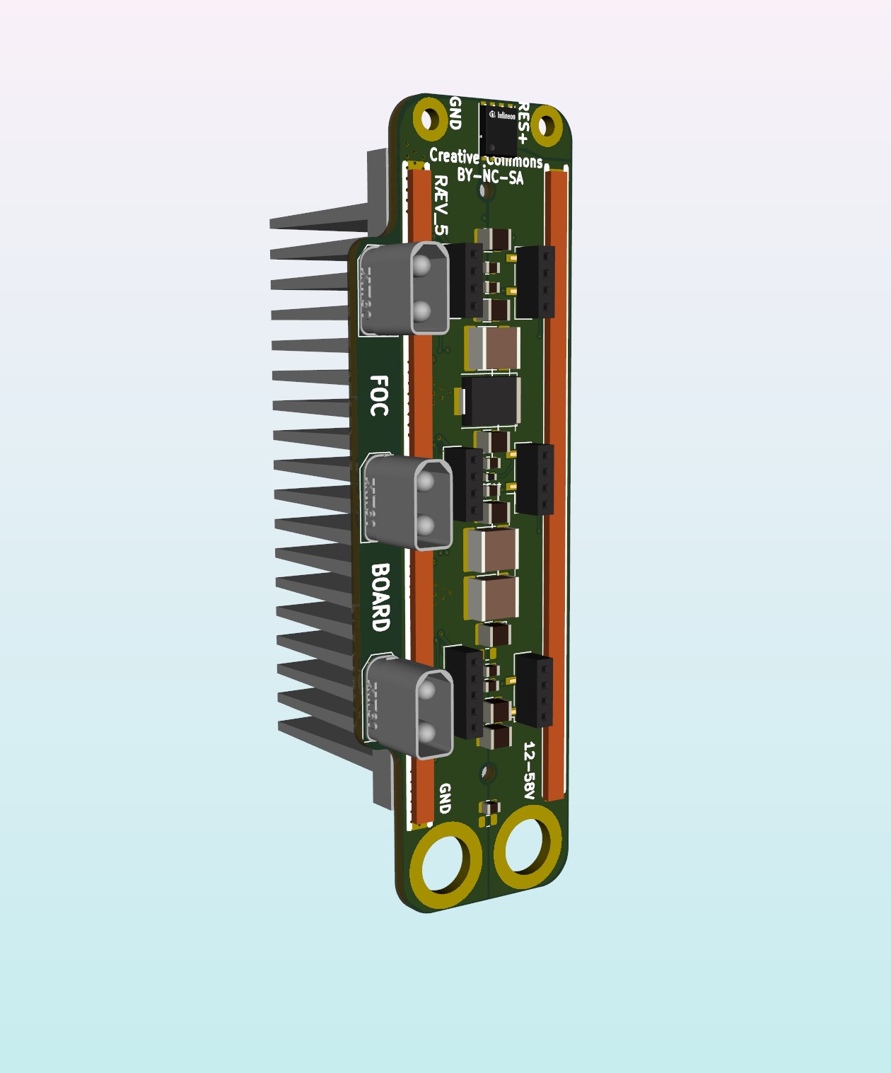
I have made some modifications. Since the shunt is not needed for the HALL_current sensor, we just as well minimize the resistance. So ive bundled the FED´s tighter together. The headers topside, stay the same. Im contemplating having a temperature probe in each phase.
Have removed those center mounting holes, since I plan to bond the whole thing with the heatsink using heat_silicone. The remaining two will more or less just align the PCB and heatsink.
@Juan-Antonio_Soren_E ,
That looks nice, mostly with the braking resistor system. I don’t know if it’s already implemented in SimpleFoc library but that’s a useful features for people who work with a power supply.
Do you really need 3 thermistors? I mean, the temperature of the phases should be quite the same, maybe only one is enough.
Yea, the breaking resistor is also usefull for direct drive setups, where you want to dissipate some heat / lower the voltage, while doing regen breaking.
I think its best to know each fase_temperature. The thermister is also very close to the CC6920 sensor, so it is also to monitor the sensors.
No, I plan on placing a CAP bank (modular) in front on the main power lines, and one axial for the brake resistor, maybe more depending on how creative you get. Those caps are unfortunately worn over yers of use, that’s why I believe this modular thing has its advantages.
I just scored 3 psc STSpin32G4. Was looking around at mouser and there they where, 3 psc left in stock. Will be fun to se how that turns out.
Dimensions: The heatsink is 80mm wide and 40mm tall/thick