Very astute, yes, this is an elegant way to do it. Of course it comes at the price of limiting your maximum torque a little (depending on the motor).
Actually personally I did not. Maybe Antun did. Perhaps we should add it as an option? Or replace the current scheme with what you suggest. Or perhaps we should introduce an offset to allow the user to choose the mid-point if desired, and default it to driver.voltage_limit/2 (the current method)?
I will discuss it with @Antun_Skuric
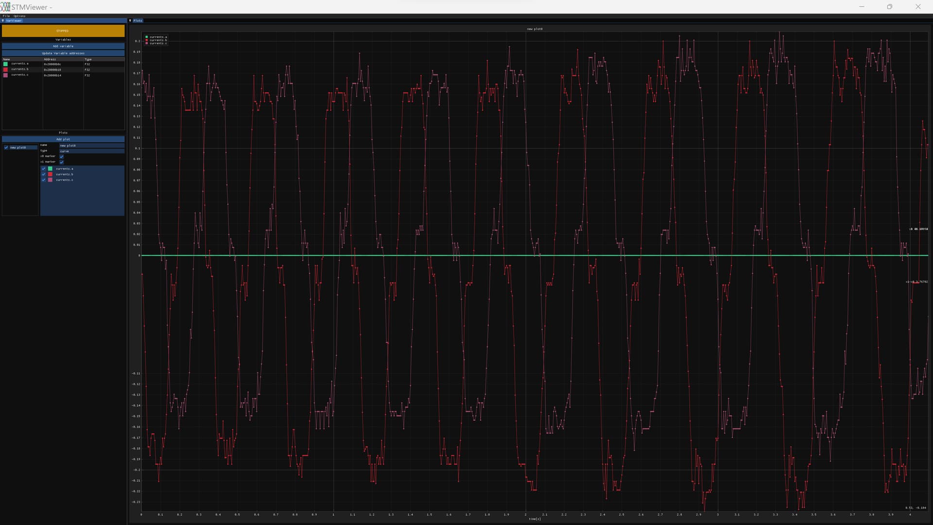
From my experience, current samples are bad at high duty cycle.
Some FOC implementations just sample the two best phase currents (lowest duty cycles), and calculate the third one, but it’s not possible with only 2 shunts.
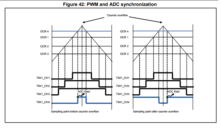
Another thing I will do is using the 4th timer channel to trigger injected adc after the middle of the pwm period, to account for the turn on time and noise. This also helps at high duty cycle. I also have an STM32 example of this, I can share it if you are interested.
I think if you set TIMx_RCR = 1 you’ll get a timer update event on underflows only.
If I’m not wrong the underflow or zero turnaround point should correspond to the middle of the low side on period.
In this way you don’t need to maintain and update a fourth timer channel.
The update event can be routed to the timer trigger out signal (TRGO or TRGO2) and used to directly trigger the ADC via the event system.
The exact mechanics depend a bit on the chip you’re using. Is this still the gigadevices MCU? Does it even have the same triggers and timers as the STM32s?
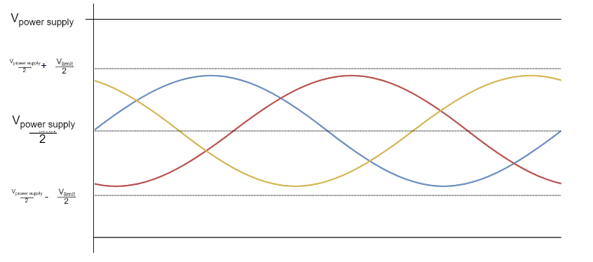
So driver.voltage_limit is the maximum DC voltage (maximum duty cycle) that you do not want to surpass using your driver. If we would center the modulation at the half of the power supply, that might already be higher that the driver.voltage_limit, in the worst case. If driver.voltage_limit is just a bitlower than the power supply voltage then centering around half of the power supply would not be in the center of the range and pozitive peaks would start to be saturated much before the negative ones.
So driver.voltage_limit is not limiting the voltage vector but the power supply voltage.
On the other hand, the variable limiting the voltage vector is motor.voltage_limit. If you set the motor.voltzge_limit then the centerin will not be influenced but the relative voltage between the phases will be limited (the voltage vector).
GD32F130 can use Timer 0 Channel 3 as trigger source for Inserted ADC (e.g. here ).
STM32F103 can use Timer 1/8 Channel 4 as trigger for the Injected ADC (e.g. here )
That’s useful if you want to trigger the ADC before of after the middle
You have a enable the channel, set it’s pulse (not 0 otherwise it overlaps with the timer update), and set PWM0 or PWM1 depending on if you want to start before or after the middle.
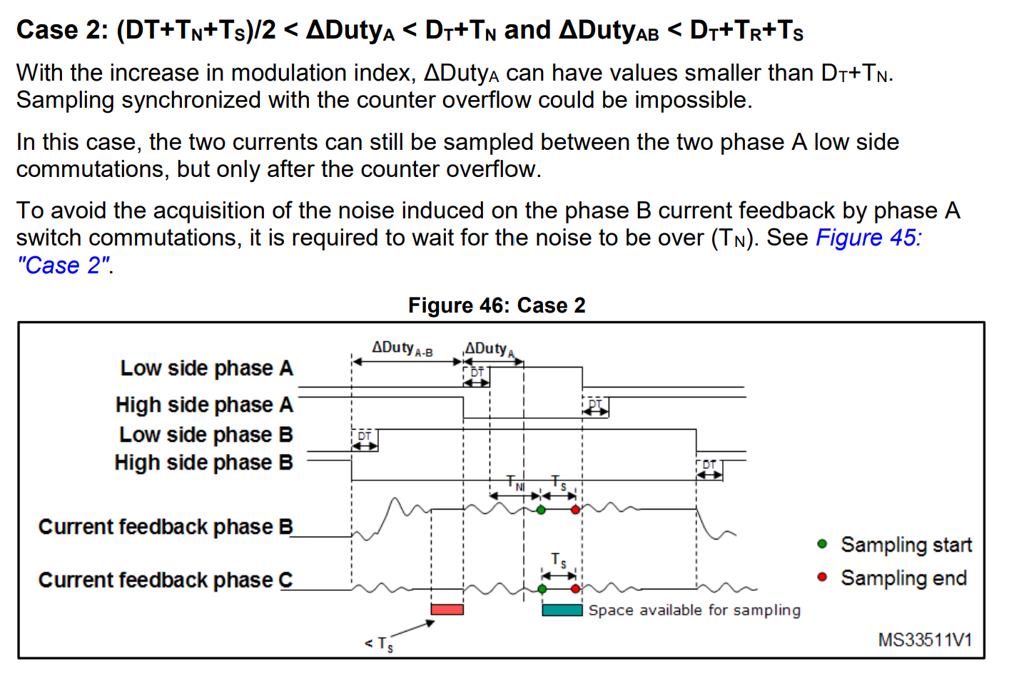
STM32 is using this in their MCSDK to sample after the Deadtime + Rise + Noise;
I just gotta say the technical knowledge and skill and background that comes to the fore here is amazing. But it’s still in aid of getting this one board working, which is not a particularly suitable board for many purposes… Which says to me that much of the skill and time being poured in may have little result for others down the line. In contrast to working on the QUADVRANS (sp?) or whatever, a board built from the ground up to be powerful, economical, compatible, and -ultimately- suitable on * all* counts.
I could have just ported Eferu’s FOC firmware to those boards, but I decided to implement SimpleFOC drivers for GD32 chips because simpleFOC has a great community and good contributors.
I hope I can then help make SimpleFOC better ( e.g. improving hall sensor support, helping with dual foc, deadtime compensation), rather than working in a silo on my own firmware.
Making boards is not my thing, I can’t really help there sorry.
I can only help with the software.
I hope the hoverboard controller went through all the stages of HW-development: FMEA, CE-certification, EMC-tests.
Maybe the chinese HW-Devs have taken some shortcuts, but the controllers we can order from JLC haven’t gone through most of them for sure.
Plus, the controllers are available for cheap (~10€ used). Just search for defect hoverboards, they usually have a dead batterie.
If we would rewire a motor to delta, could we use both power stages for one hot motor? (delta uses 1.7 times the current)
Using MOSFets in parallel is a common thing…
Those are 2 different things.
Delta wiring is not a problem as you can see here.
With Simplefoc in foc current mode it should work.
I have never tried running a single motor with both 3 phase inverters.
Usually controllers with parallel mosfets only have the mosfets in parallel, you cannot drive those mosfets independently and you don’t have separate hall sensors and current sensing.
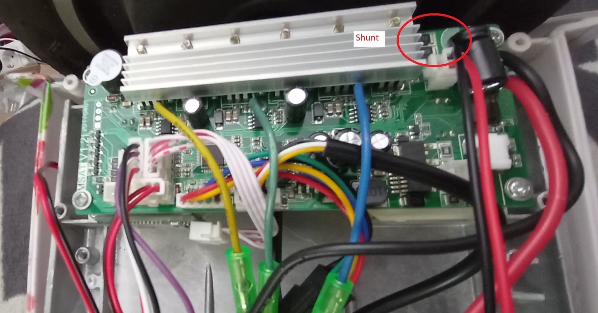
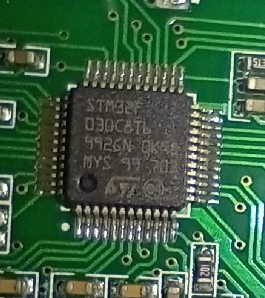
I got two more 10" hoverboards with split controllers. They feature a STM32F030C8T6 MCU, which none of the known hoverboard hacks seem to support.
What would be the bare minimum I need to figure out to make them run with sFOC?
Halls and motor phases obviously
current sensing (it only has a dc shunt)
power switch logic?
some control input (commander and serial don’t fit in 64k flash it seems)
It only has 64k flash. I tried to compile the bluepill_encoder example and it didn’t fit by a few 100 bytes (164 IIRC)