There are some voltage regulators, the LEDs and 2!! blutooth modules.
When I switched the board on, I got a english spoken message over the speaker. There seems to be some extra memory for that stuff.
I figured out the H_in and L_in pins for each gate driver and the three hall sensor pins.
Do I have to use 6PWM mode or can I use 3PWM and ignore the L_in pins?
What else do I have to consider for a first test run? The MCU is part of the STM32duino, so I guess, the pin definitions are already there.
It was no surprise, they took the TIM1_CHx and the complementary TIM1_CHxN pins for the FET drivers.
The Hall pins are all on different registers. Is it on purpose for better interrupt control?
Absolutely not… if the hardware is designed for 6-PWM then you have to use 6-PWM…
Which Board definition are you using and what clock speed does it configure for the MCU? You may need a clock setup function. Does the board have an external oscillator?
On the dual controller and the single controller I experimented with, we had to use this SimpleFOC parameter:
SIMPLEFOC_PWM_LOWSIDE_ACTIVE_HIGH=false
Getting it wrong means overshoot/short circuit, so my only hint is to use a power supply for current limiting lol
Those hoverboard controllers usually have a latch that you have to keep High in your code but if you connect the stlink 3.3v and GND it should stay on.
The pole pairs is 15.
I only used the inductance for now (0.00036858H), which compensates for the lag as the speed increases.
Here is the code I am working on for another board, I need to clean it up… But it might give you some hints.
Ideally I will create custom board variants and add different chips (from stm32 and gd32) to pick up from in the platformio.ini knowing that:
not all boards have phase current sensing so not all can do foc
some have dc current sensing that could be used for current limiting (not supported by simpleFOC yet if I understood well), some have only an overcurrent trigger that could be used for break input (I implemented this but only for gd32)
Hi,
that’s a very good starting point for me. Thanks for letting us peek.
I haven’t figured out the shunt-pins, so I’ll try to use FOC in voltage mode. That worked pretty well with small gimbal motors.
How important is the correct inductivity of the motor? I have 6.5" and 10" hub motors. ( Not to mention my 5kW e-bike hub motor :evilgrin )
I hope I can sort out all the experimental stuff in your code and shrink it down to the basics.
If there is no opamp the shunts are probably just used for overcurrent trigger.
Inductivity is not so important at the beginning, I needed it so the motors as fast as I expected. This value will be different depending on the motors, that’s why I thought I buy a lcr meter to measure it on most common motors. The hoverboard motors have different size of magnets and number of coil wires, this impacts the KV rating/resistance/inductance.
As you can see in this repo, there are many variants, and more are coming.
I could identify an opAmp SD06. It’s far away from the shunts, so I didn’t think they are related.
'll track it down, but even if it’s a lowSide shunt DC-shunt, sFOC doesn’t use it? (your words)
I have checked the other forks of Eferu trying to make good use of the split boards. My PCB-version isn’t listed there. No other board uses the M0 MCU it seems…
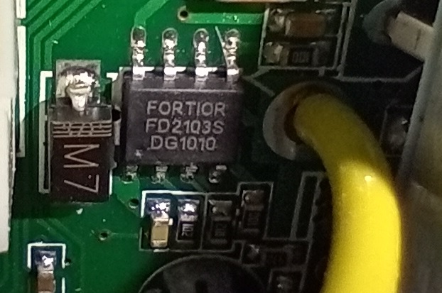
When they use RDSOn as shunts, there would be more opAmps or does the gate driver chip support that? (Fortior FD2103)
I only found a chinese? datasheet for them. Gladly they used english to describe the pin names, or I’d been busted…
You can print out the value of F_CPU, it should contain the CPU speed in Hz.
If it isn’t right you’ll have to supply an STM32 clock init function. Arduino IDE won’t really let you configure the missing bits for generic MCU definitions, you have to do that in code/configuration.
For simple tests it is not important, but for reaching optimal performance (especially if you want to go fast) it can help.
It is critical to get this right, or it will not work (best case) or it could even cause a short and burn up your driver board.
By getting it right I mean ensuring that the driver is supplied with the expected PWM polarity for all the FETs. If the datasheet is in Chinese, it still often includes timing/PWM waveform diagrams that can be understood without the text.
I think you can definately try it and see how it goes. The PIDs would only apply if you used velocity or position modes, not in torque-voltage mode.
The problem I see is that the current waveform may not be ideal due to the voltage control, but I guess you won’t know if its really a problem unless you try it…
No, the default value is active-high, so SIMPLEFOC_PWM_LOWSIDE_ACTIVE_HIGH=true, because this is both the way it always worked in the past, and what 90% of the hardware expects.
Well if you’ve run SimpleFOC, you know that’s not the case
All of the SimpleFOC hardware, and all of the commercially available driver boards that interface with a MCU all use active-high polarity, AFAIK. It’s only self-made or re-purposed hardware that has this active-low situation.
Someone who is reverse-engineering a PCB like you’re doing needs to consider these details. Someone who buys an off-the shelf driver normally does not. I think spitting out warnings that 95% of our users would have to ignore would not help the situation, and cause a lot of support effort.
Reverse engineering a PCB is one thing, but digging through the complete code of simpleFOC to find some traps is another.
Until today, I wouldn’t have heard about the PWM_low_side thing…
Wondering which surprise is awaiting me next?
I’m only using these boards, because they are cheap enough to try.
I’d gladly use off_the_shelf drivers or AIO-boards, but they are often evaluation_only boards.
They’re not designed to be traps, but instead offer more configuration for people who need it. I think they are all documented here:
Note that even more build flags exist (in general), but can be hidden in the Arduino core, or even the language itself. As you need them you will find them, I think.
Thanks, that’s very helpful, but also a bit discouraging.
I’ve already identified two drivers with low_active L_in: the FD2103S and the “EG2133” I found on MKS dual FOC+ boards.
It’s a critical setting that can cause severe damage. Of course we are advised to use a current limited Lab supply, but still. my spider-sense tingles
Another downer:
I’ve tried to connect the SWD port to my ST-Link to see if I can unlock the chip.
But I only get can’t reset MCU errors. Tried different frequencies and connect under reset options. But always the same…
I would certainly do this for any hardware where the configuration is unknown! I think this just comes as a requirement with the task you are trying to perform.
In order to synchronize with the device, it needs to “reset” the chip so that it can start from a known point. Do you have the reset line hooked up to the board? If reset is not exposed on the SWD connector, I think “connect under reset” means that you manually reset the chip (e.g. power cycling) and it will grab a connection right when it starts up.
Which STLINK are you using? A real V2, clone V2, a V3?