I searched the forum and wiki but can not find a definitive answer. It seems there were some abandoned attempts, but I do not see for sure a definitive result, so I ask the question
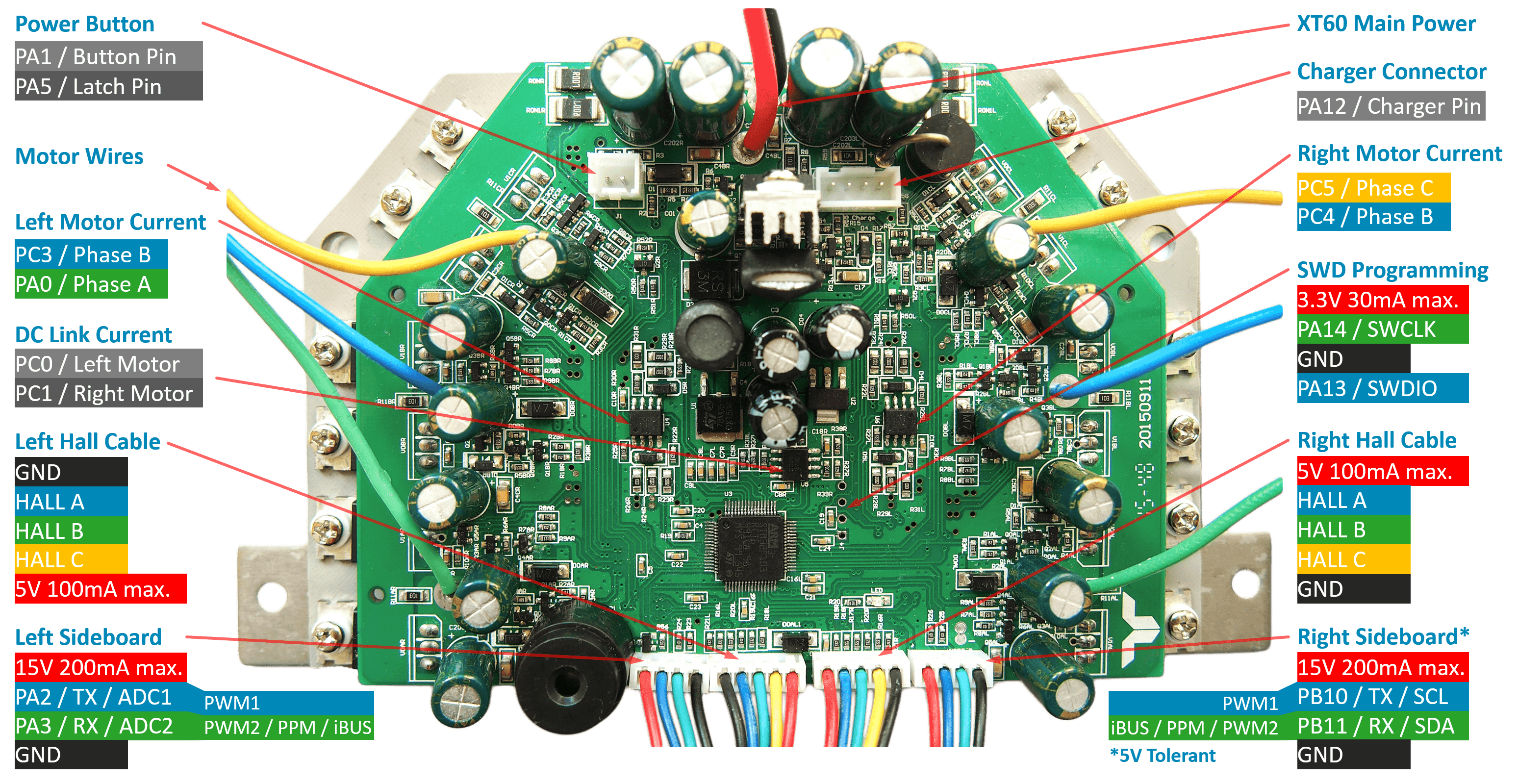
Is it possible to use SimpleFOC on motor control board for hoverboards, such as this one
schematic:
It seems everything is implemented (6PWM ?) but I am not sure the current sense control is supported by SimpleFOC on these boards. If I understand correctly the schematics, they have total current sense as well as for two out of three phases per motor.
Anybody tested that configuration ? I do not want to reinvent the wheel if someone has made someprogress on this already.
The reason I am interested in bringing SimpleFOC to this and not other firmwares, is that SimpleFOC has position control and seems much more flexible overall.
ok that is very encouraging. I see in the docs that 6PWM is supported and the pinout for one motor is exactly what is needed to use hardware timer 1 on stm32. I see the second motor uses the corresponding pins for timer 8. I assume SimpleFOC does the mapping correspondingly for the second motor, I have not yet verified in the code.
One thing I am not sure is the current sense. I am not sure if it maps to any supported scheme (low side, inline high side).
My understanding is that this board can measure the total motor current, and the voltage between the phase top and the low side total current shunt. It would make sense that from that phase voltage can be derived the current in that phase, isn’t it ? But is that really analog to measuring the low side phase current ?
If that is the case, I suppose it would be possible to compute the phase current based on the phase voltage, motor winding impedance, and total current. Any thoughts ?
Also, how important is the current sense ? Can this still work well overall without current sense ?
For current sensing, we can currently only support one motor. We are working on supporting multiple motors, but it’s a non-trivial task to do this in a general way, so it might be a while before SimpleFOC supports current-sensing of two motors on one MCU.
In terms of at least getting current sensing for one motor, I assume this is a low-side 2-shunt sensing configuration, but the schematics you link are confusing me. Perhaps I’m just being blind, but I can’t actually find the shunts in the schematics, and can’t see how they connect to the op-amps.
If it turns out I’m right and it’s 2-shunt low side sensing, the. It should be supported for one motor at the moment. Same if it’s 2-shunt in-line sensing.
The schematics include an over current op-amp, and while we don’t have code to support this, it could be implemented based on interrupts, and this could be quite useful…
In terms of VBUS sensing, we currently don’t support it, but are working on it.
This sounds like 1-shunt sensing, which is hard, and we currently don’t support it…
But the schematics kind of indicate it has 2 shunts per motor?
yeah I am a bit confused by how the schematic works, but it is correct, I actually reverse engineered all of it, then found that schematic I linked to and checked it absolutely corresponds to what I traced from the PCB. So, it’s accurate
It does not have 2 shunts per motor, you see there are two parallel resistor shunt between -VBatt and the Hbrige GND side for each phase, so that measures the total current for all phases, it goes to an amp on current_sense.sch, one for each motor.
the schematic named phase_sense.sch has two opamp circuits which from what I gather, sample the voltage for phases A and B of right motor, respectively phase C and B for left motor. I agree with you, that does not look like current measuring as it samples the voltage not across a shunt resistor but across the phase and the top of the common shunt for all phases. So, really, it is straight measuring the voltage across the winding of the motor.
I am not too versed in motor control (yet haha) so I do not see why measuring current is done across a shunt, if we measure voltage instead can’t we just use U=RI to derive current ? maybe with some dynamic adjustement since current and voltage do not have the same phase ?
well I am interested in configuring this for autonomous robot platform, and also for precise position control (robot arm). It seems that can be achieved satisfactorily without current sense, can’t it ?
Yes, I think it can. Current measurements are needed more for precise torque control, and to keep low ohm high current setups under control.
Position control is quite possible without.
Ah, ok! Then that’s a single shunt low side configuration (the fact that there are 2 resistors in parallel is just to make them get less hot / survive higher currents, and can also be good for precision since their variations may cancel). And unfortunately we don’t support it.
Hello, this is a very exciting project. I recently bought 2 second hand hoverboards. The first one has the original mother board described in your subject. I managed to build EFeru firmware with platformIO, flash it on the board, then drive the 2 wheels via USART from an ESP32/Arduino. The speed control is good enough for my prototype so I did not think I would need SimpleFOC. As my prototype requires 4 wheels, I had a bad surprise when I checked the second hoverboard. which has the so called splitboard described here: GitHub - Candas1/Hoverboard-Firmware-Hack-Gen2: Hoverboard Hack Firmware Generation 2 for the Hoverboard with the two Mainboards instead of the Sensorboards (See Readme.md). . EFeru firmware was ported on this splitboard to some extent, but I do not want to support different drivers on my prototype. It seems that this newer splitboard is more common than the original one, and I like its modular design: each board drives 1 wheel, so it could be suitable to many projects. You can find the documentation of the GD32F130C8 MCU and a description of the board’s IO ports in the link above. One of them supports I2C.
Instead of trying to port SimpleFOC on this splitboard, I wonder if I could not use it as a kind of SimpleFOCShield and drive it via I2C from an STM32 black pill running SimpleFOC. Basically, the firmware running on the GD32F130C8 would simply read PWM frequencies from I2C, drive the Mosfets, then send back hall sensors signals to I2C. If I can setup a different I2C address for each of the 4 splitboards, 1 STM32 black pill could drive the 4 wheels using SimpleFOC. Do you think it could work ?
I have the GD32 splitboard and I estimated that making it work is too much (boring) work for me.
If you go that path, remember that SimpleFOC will probably work with GD32 (in theory it should), but you need to either reverse engineer the board or find someone who already did it. Pls share your findings if you decide to tackle reverse engineering.
Just make sure the MCUs have enough memory to accomodate SimpleFOC.
There is an I2C commander written for SimpleFOC that will allow you to send/receive commands to the motors from a central MCU via I2C (if using SBC, you will need to write your own sender). It supports multiple motors per I2C address as well as multiple I2C targets (simplefoc controllers)
I probably misunderstood initialy:
Are you trying to use third party firmware and would like simpleFOC to send commands to a different firmware? If so, when you say read PWM, do you mean to read the required PWM for all phases?
Absolutely. The idea is to write a simpler “third party” firmware on the GD32 and use SimpleFOC to send commands to this firmware. I guess that these commands would be the PWM for all phases. The bottleneck of this strategy is probably the amount of commands to send and feedback (hall sensors) to receive via I2C. STM32 I2C bus can support up to 100Kb/s, but I’ve no idea of the required data rate sent by SimpleFOC ? Would it depend on the actual motor speed ?
What you are proposing is not possible without re-writing SimpleFOC algorithm which creates a catch-22, if you have the knowledge and skills to re-write it then you won’t need to do that. Also i2c simply doesn’t have the bandwidth. You need something like full duplex 10MHz SPI to get data back from the current sensors, etc. It’s going to be a nightmare.
The way I see it, your best option with simpleFOC is to make it work on GD32 board (if that’s possible) and send velocity commands to all 4 wheels via I2c.
Exactly - since gd32 are supported by Arduino framework (and are functinally very similar to STM32s), SimpleFOC should work with them. You can probably remove everything you don’t need from simpleFOC framework to reduce the final elf file size and make it fit on MCUs with smaller flash size.
There’s a minimal branch for this https://docs.simplefoc.com/minimal_download
You can give it a try - if you do, please let us know how it goes.
Personally I would use PlatformIO rather than ArduinoIDE because the error messages are clearer and better, which is useful when doing this kind of thing.
Apparently this framework version runs in PlatformIO.
Anyway, once you have the framework installed in the IDE, you can just install the SimpleFOC library normally, but I would not expect it to work…
This GD32 chip is a clone of the STM32F103, so it should be able to do similar things, but in order to be able to control motors, SimpleFOC has MCU-specific PWM initialisation code… we have 14 different MCU types, but GD32 isn’t one of them
And even though it is like an STM32F103, it doesn’t look like the Arduino framework for it has the same APIs as the STM32 framework does. Our STM32-specific code uses the STM32 HAL (hardware abstraction library) to do the PWM initialisation.
So I’m guessing the exercise to get this working will mean writing a PWM driver (and if you want current sensing then also an ADC driver) for it…
Dear sir,
I study the FOC driver (at link you listed) and even tested it. I found that the UART communication between robot controller and driver only handle two motor with one command, and when made FOC ad ADC/PWM the two motors not accurate positioning (i.e. one motor start fast than other) and so robot rotate (i.e. motor not synchronous together even with same ADC values applied to each motor-side).
Are you have solution to make the FOC driver : run motors synchronous if same ADC/PWM applied to them, second how to control each side by different commands (by UART) that may make two side work with same speed and position.