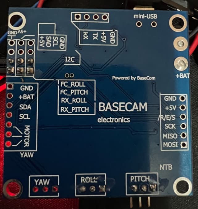
Here is the entire pinout option pictures… Hope i can use this 3-pin option.
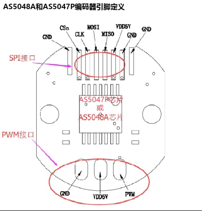
This version of the encoder only has the PWM pin wired. Using PWM mode is not recommended!
To use SPI you’ll have to solder wires to the other pads on the other side of the sensor board…
What @runger said, but you’ll still need the two wires for VCC and GND
Thank you @runger and @o_lampe for confirming. I reached out to the supplier to provide exact pin details…posting it herewith…might be useful to others, just in case they have the same chip …
Here i will connect 6 wires from the top side (SPI) and a ground + VCC from the bottom one PWM pinout right?
You could also connect GND and VDD to the other header by soldering new wires. Either way will work. Using the existing power wires means less soldering, but then the wires will be coming out 2 sides of the encoder…
1 Like
There seems to be a cutout in the housing for the wires, so you’d have to route the extra wires along both sides of the chip.
I think it would be less hassle, if you keep the existing VDD and GND wires…
1 Like
Thank you again @runger and @o_lampe. Today I ordered a few LJ12A stop switches and HC-SR04 ultrasonic sensors to test them out. I am going to implement the charge connection and a secondary check (either a switch or ultrasonic sensor) both.
For SPI pins it is all clear to me (almost). I was just not sure about the yellow coloured wire - is R/E/S to CSn a correct match? After making others, that was the only one left so hopefully it is right.
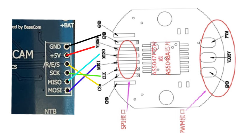
Yeah it’s a weird label for this pin, but by elimination it has to be the nCS pin ![]()
1 Like
Hi guys, the standard position control example in Simple FOC defines encoder with…
// encoder instance
Encoder encoder = Encoder(2, 3, 8192);
Do i need to change anything here for AS5048?
The AS5048 IIRC is an SPI magnetic angle sensor so… the Encoder means a device using an optical interrupter and a rotating disk, in this case apparently with 2 output lines, and the third number there indicates the pulses per revolution.
The AS5048 could probbably be programed or set up in some way to give such an output, however you probably want to use the SPI interface instead. There are example you can find in Arduino for how to interface to common SPI based sensors (they can be called encoders but magnetic angle sensor is the proper term in this case). Best to find some snippet on the forum or in the examples that is known to work exactly in this context of yours, because small details can mess up the readings etc.
1 Like
Check with the tester where the R/E/S pin is connected.
When I made a self-balancing bike with this board, I connected CSn to pin 14 (Arduino).
MagneticSensorSPI sensor = MagneticSensorSPI(14, 14, 0x3FFF);
Thank you @Rem666 and @Anthony_Douglas
@Rem666 - in regards to the R/E/S, my board traces look identical to the photo you posted. So, should i solder it across with the wire like in your photo?
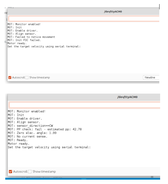
After running the correct code, first motor moves slightly and slowly and here a lot of noise, then noise continues. nothing happens. In serial monitor, it shows the following:
MOT: Init
MOT: Enable driver.
MOT: Align sensor.
MOT: Failed to notice movement
MOT: Init FOC failed.
Motor ready.
Set the target angle using serial terminal:
@Rem666 If I connect the RES with wire - same as your board, then its stops making sound and a little green light starts flashing. However, still T100 or such commands dont work through the serial port. I have also used pin 14 when defining it in the code…MagneticSensorSPI sensor = MagneticSensorSPI(14, 14, 0x3FFF);
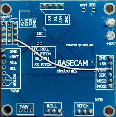
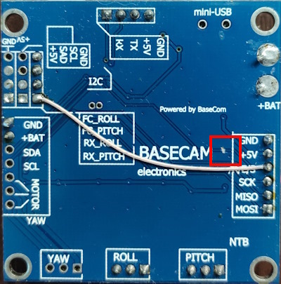
You need to think about what you are doing. ![]() This PIN is already connected to atmega. You need to cut it first. I marked it in red.
This PIN is already connected to atmega. You need to cut it first. I marked it in red.
Thank you @Rem666 - sorry missed that part. Now, after removing that original connection, it makes a slightly different noise when connected as per your wire. However, it still fails to move. I tried changing motor voltage etc. in this standard example. If you don’t mind could you please have a look…does this look right to you?
/**
 *
 * Position/angle motion control example
 * Steps:
 * 1) Configure the motor and magnetic sensor
 * 2) Run the code
 * 3) Set the target angle (in radians) from serial terminal
 *
 */
#include <SimpleFOC.h>

// magnetic sensor instance - SPI
MagneticSensorSPI sensor = MagneticSensorSPI(14, 14, 0x3FFF);

// BLDC motor & driver instance
BLDCMotor motor = BLDCMotor(11);
BLDCDriver3PWM driver = BLDCDriver3PWM(9, 10, 11,  8);


// angle set point variable
float target_angle = 0;
// instantiate the commander
Commander command = Commander(Serial);
void doTarget(char* cmd) { command.scalar(&target_angle, cmd); }

void setup() {

  // initialise magnetic sensor hardware
  sensor.init();
  // link the motor to the sensor
  motor.linkSensor(&sensor);

  // driver config
  // power supply voltage [V]
  driver.voltage_power_supply = 12;
  driver.init();
  // link the motor and the driver
  motor.linkDriver(&driver);

  // choose FOC modulation (optional)
  motor.foc_modulation = FOCModulationType::SpaceVectorPWM;

  // set motion control loop to be used
  motor.controller = MotionControlType::angle;

  // contoller configuration
  // default parameters in defaults.h

  // velocity PI controller parameters
  motor.PID_velocity.P = 0.2f;
  motor.PID_velocity.I = 20;
  motor.PID_velocity.D = 0;
  // maximal voltage to be set to the motor
  motor.voltage_limit = 12;

  // velocity low pass filtering time constant
  // the lower the less filtered
  motor.LPF_velocity.Tf = 0.01f;

  // angle P controller
  motor.P_angle.P = 20;
  // maximal velocity of the position control
  motor.velocity_limit = 20;

  // use monitoring with serial
  Serial.begin(115200);
  // comment out if not needed
  motor.useMonitoring(Serial);


  // initialize motor
  motor.init();
  // align sensor and start FOC
  motor.initFOC();

  // add target command T
  command.add('T', doTarget, "target angle");

  Serial.println(F("Motor ready."));
  Serial.println(F("Set the target angle using serial terminal:"));
  _delay(1000);
}


void loop() {

  // main FOC algorithm function
  // the faster you run this function the better
  // Arduino UNO loop  ~1kHz
  // Bluepill loop ~10kHz
  motor.loopFOC();

  // Motion control function
  // velocity, position or voltage (defined in motor.controller)
  // this function can be run at much lower frequency than loopFOC() function
  // You can also use motor.move() and set the motor.target in the code
  motor.move(target_angle);


  // function intended to be used with serial plotter to monitor motor variables
  // significantly slowing the execution down!!!!
  // motor.monitor();

  // user communication
  command.run();
}
In serial terminal, it fails to notice movement. However, it recognises movement if I manually spin the motor while in initialisation mode. Both pictures included herewith:
You can’t use 9,10,11 for motor. SPI uses the same. Use 3,5,6.
Maybe this helps GitHub - remrc/Reaction-Wheel-Bike
Thanks @Rem666 but looks like 3,5,6 does not work for me. I checked openloop again which was working with 9,10,11 but does not work with 3,5,6. Any other pins I can try?
Finding it a bit strange, 3,5,6 works for you with the same board but it fails me. I see in your code you have included servo.h and defined servo pin, is that the reason?
Also, mine is Atmega328P. Yours likely to be the same but just in case…
Last one I hope…does order of the 3 phase pins matter?
3,5,6 pins must work. Open loop also. With SPI sensor you can use only these pins.
To me it seems there are several versions of the board.
If it works with pins 9-11 on one version, you have to figure out which other pins for SPI they have used. (or if there is no SPI available)