This board designed for two motors. And always 3,5,6 and 9,10,11 pins. Atmega 328 cannot give pwm on other pins.
Order of the 3 phase pins not matter.
servo.h is not required.
also with this board.
This board designed for two motors. And always 3,5,6 and 9,10,11 pins. Atmega 328 cannot give pwm on other pins.
Order of the 3 phase pins not matter.
servo.h is not required.
also with this board.
Thank you for reconfirmation. Its working now!
I had almost given up on the board. The board has 2 motor connections. Looks like the pins 3,5,6 in this board are for the first motor connection marked 'PITCH" and does not work for the other connection marked ‘ROLL’. For ROLL, only 9,10,11 works.
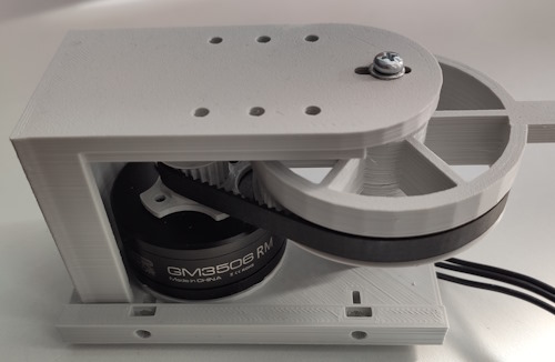
I am going to use this as a drive wheel for a carriage running on cable. So, it needs a bit of torque, no speed needed. I am currently testing with 3506 gimbal motor. The cable/wire will not have more than 15 degrees of slant and the carriage is only 400 grams. I have a few questions around my setup:
The motor’s rated nominal power is 12v. So, is it ok for me to set motor.voltage_limit = 12 ? I read a few threads about it and I am still a bit confused.
Also, for me to achieve higher torque, is there any settings important like keeping velocity lower etc? Basically, I need no speed, only the power to make sure that it moves slow and steady.
The last one…I am using gimbal here because i need outer rotor to use it as a hub wheel. It is also sort of waterproof which is a plus for me. The motor seems a bit powerless to me if I try to stop it. Currently running it at 6v limit. So, would you suggest any other BLDC with outer rotor for my use case? I know its not a hardware forum but just in case someone might have tested something similar use case. OR…are there some settings I can play with?
P.S: I do want good torque output, however, position control is important and so that is why I did not test the torque examples. Asking here if there is some way to do position control and achieve good torque.
Thanks again.
You’re not the only user who fell in this trap.
After reading many threads and the docs you will eventually find out, that the motor voltage limit should usually be 50% of the driver voltage limit.
Don’t worry, the motor will still see 12V, but the definition of it is a bit confusing. The motor voltage is centered around 1/2 driver voltage limit and swings both ways with an amplitude of +/- motor voltage limit.
Now I tried changing the voltage limit to 6V.
voltage_supply = 12;
voltage_limit = 6;
No difference at all. Strange…
If you need more torque, do something like this:
That’s confusing. We should try to stick with a convention, pick something and stick with it, basically thinking of the motor as analogous to a dc brushed motor is probably a good idea imo. So motor voltage should be the total differential between terminals.
Yes, but even on a brushed DC motor you can go in two directions? So voltage can be either positive, or negative, depending on the direction you want to go…
In this case it is the Q axis voltage which is limited by the motor.voltage_limit, and controlled with the motor.target (in torque-voltage mode). It’s a nice analogue to the way a DC motor works, control by voltage, but of course it is not exactly equivalent to the motor terminal voltage of such a motor.
After all, the DC motor only has 2 terminals, while the BLDC has 3, so which terminal-to-terminal voltage would we even be referring to?
Well the input to the h-bridge, or it’s equivalent (given the average duty cycle of the transistors). Also, the maximal rpm the motor achieves vs said voltage, with optimal motor timing. Like, as if the KV rating was being applied to calculate the maximal rpm no-load. Right? That way we can compare things apples to apples to some degree.
You can use it to calculate current at stall using ohms law, and the maximal no load rpm you would ideally be getting and stuff like that.
So, we apply a series of tests in various circumstances and see if the results match an intuitive notion. So, like, if the power supply is set to 12 volts, the driver voltage limit is 12 volts and the motor is set to 12 volts, you get full power? The maximal that can be applied with the power supply voltage being whatever it (actually) is.
I kinda think SimpleFOC already does that, at least as far as is possible.
The driver voltages are absolute, so they correspond to the PWM output “voltage” of each phase
But in a rotating 3-phase system you just have to get comfortable with the idea that the phase voltages are meaningless without the rotor angle information to go with them. The torque produced depends on the angle of the rotor. So depending on the rotor position, the same phase voltages could result in maximum torque in one direction, zero torque, or maximum torque in the other direction, or anything in-between.
That’s exactly where the motor voltages come in, and the Clarke/Parke transforms and their inverses. Using this maths you can transform the 3-phase system into a stationary 2-axis system which rotates with the rotor. In this system, you can express voltages in a way where they correspond to torque/speed produced in a meaningful way.
Using this abstraction, you get the nice behaviour of being able to control the motor in torque mode by directly setting a voltage (or current, with current sensing or estimation) and having voltage/current correspond to signed (i.e. motor direction) torque.
Yes, creating or using gears will surely help with the torque, however, in my use case I need to use it as a hub wheel. In fact, its the major reason for moving from DC to outer rotor BLDC. I need it to be water resistant as well. So, the gimbal motor was an ideal choice as it kind of offers both advantages. Would you suggest any parameter tweaks or an alternative motor profile to use as a hub wheel?
As per your suggestion on another topic, I am going to set the motor voltage at 6v and driver voltage limit at 12v. However, in case if the torque is not sufficient, would it be safe to go 12v for motor if our use case is to run it for few mins and then shut down for few mins before starting it again?
The max. motor voltage wouldn’t change, but the wave-form would be less optimal (more square- than sine-wave)
The motor get’s noisy and wastes a bit more energy.
Got it. So no point doing it.
So far its all progressing well in my testing. One question relating to code to which I cannot find answer in the documentation…
How do I setup my motor to gradually slow down when approaching a target? Especially when approaching 0 target, I want my motor to gradually reduce its speed.
(sorry one more)… How do we query/get current position? Like MC gets me current motion control mode, is there a way to get current position?
This is a control loop you will have to add yourself. It is not hard to do: you can limit the motor’s speed in position mode using motor.velocity_limit.
So you can add a check to get the current position:
float delta = motor.target - sensor.getAngle();
and then use it to constrain the speed:
float max_speed = fabs(delta / 0.5f);  // set speed so that we stop in 0.5s
if (max_speed > 100.0f) max_speed = 100.0f; // prevent speed limit going too high
if (max_speed < 0.25) max_speed = 0.25f;   // prevent speed limit going too low
motor.velocity_limit = max_speed;
Note you can also play with the PID values for angle_P and velocity_PID and the LPF filter values, you may be able to get behaviour you are happy with based on that too.
Thank you @runger !!
This is going to be very useful alongside proximity sensors. Now, for a similar use case, where we get proximity alert (too close) and need to immediately stop the motor… will it be a best option to get voltage to 0 or would you recommend to do it any other way?
Btw, I looked at the examples, they are good to get started, however, could not locate any comprehensive examples involving different scenario management with advanced options. Me being new to this, have a limited creative ability to think something advanced…Would anyone be able to point me to somewhere I can look at more advanced examples?
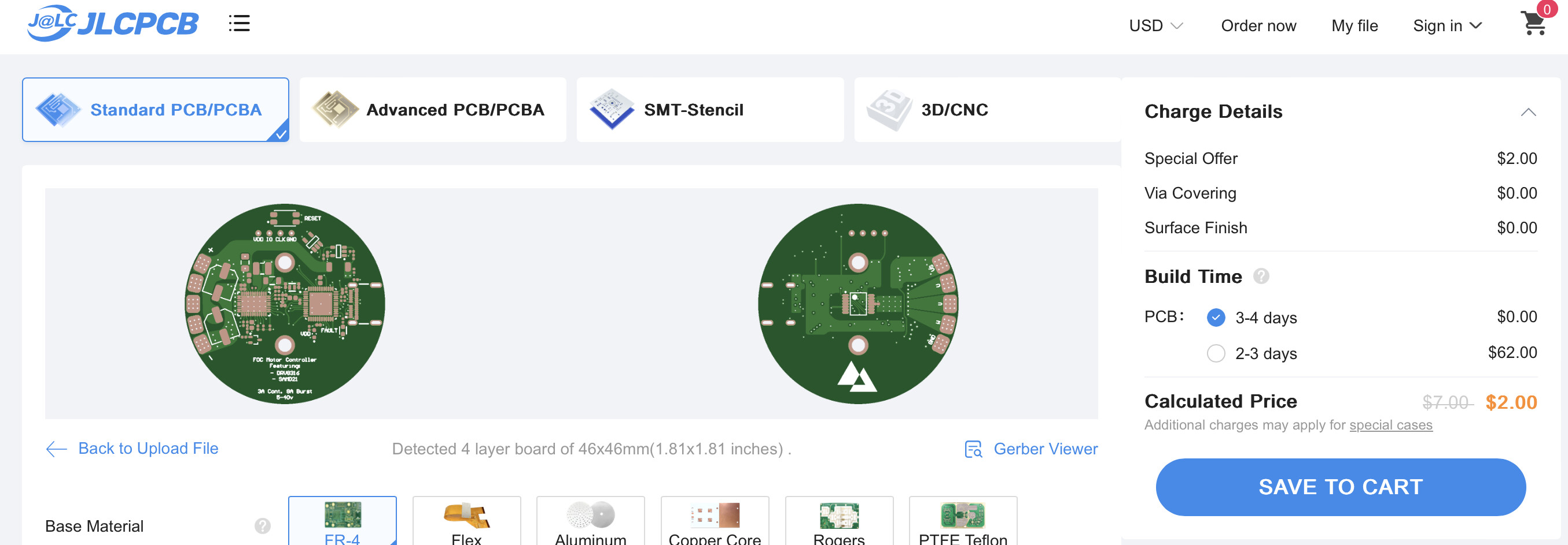
One more question team… I am thinking of getting this one printed
GitHub - AdinAck/Motor-Controller: An FOC motor controller based on the SimpleFOC library, featuring the SAMD21 and DRV8316. by @AdinAck . I hear that its been designed with your help @runger ![]()
PCBWay is quoting ridiculous amount. Any suggestions on where to go to get these manufactured?
May I ask how much they are quoting for it?
And may I ask what are the features that make this one right for you? Is it the SAMD21 you like, the DRV8316, the form-factor, or is it a combination of everything?
2 bucks on JLCPCB.
Keep in mind I made this board in high school and it’s probably not ready for any prod usage lol.
But if you really want to use it I have made five of them and all worked, so, it will probably work for you.
Also hi @runger ![]()
![]()
Hi @runger
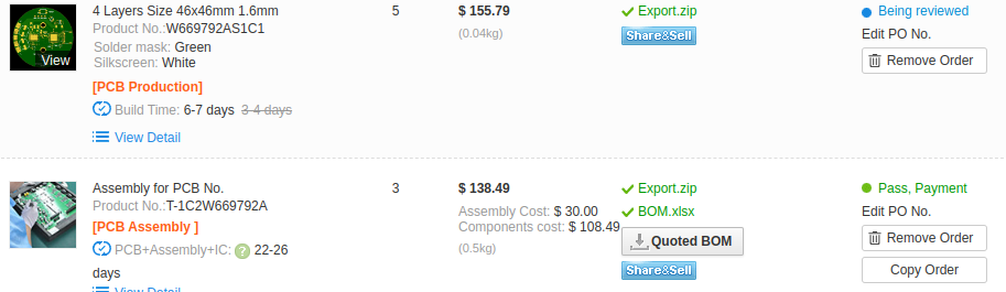
They are quoting around US$155 for board and total around $300 including parts and assembly for 3pc. See attached.
Two reasons I am considering this board: 1) DRV8316 and 2) form factor. It will fit nicely for 4108 or 5208 motor. Its tidier with controller tucked in with the motor. Do you think its suitable to use in production? Would you suggest any alternative that may be widely tested and you would recommend? - one which does not require me to sell my kidney ![]()
wow, that’s a lot cheaper compared to what I’ve been quoted. Exhibit A in the previous post!
Yes I was thinking of using it in production use. Would you suggest any alternative?