No idea about steppers. However:
角度线性误差 <±0.35° from the documentation means angular non-systemic error less than 0.35°
Which means 360° is divided into 1024 error-free steps or 10-bit error free if you do not use any filtering.
No idea about steppers. However:
角度线性误差 <±0.35° from the documentation means angular non-systemic error less than 0.35°
Which means 360° is divided into 1024 error-free steps or 10-bit error free if you do not use any filtering.
I doubt it. If you search this forum, other users have had trouble with the high pole count steppers even when using 14bit sensors, and this one is only 12bit.
I think this sensor will be suitable for lower pole-pair motors, maybe up to 11PP or so?
That’s 4000 positions. Perhaps an optical graycode encoder, but those are more expensive than the stepper. Cheapest I’ve seen are $50 and more.
https://www.digikey.com/en/products/detail/cui-devices/AMT203S-V/9739186
Sure I just noticed this aspect in the data sheet.
Here is an English version of the data sheet: https://semiment.com/wp-content/uploads/2021/04/SC60228_EN-VA1.0.pdf
Still. 2^10 = 1024. That’s roughly equivalent to equivalent to a regular stepper driver with 4 micro steps. (4micro/full*200 full steps/rev = 800 micro steps/rev). Still I don’t how the accuracy effects the speed and position estimates in this library.
I got the 14 bit AS5048A working great earlier to day (1 prototype).
The AS5048A has even worse (perhaps more accurate specs)
Thanks for the answers. I will not be too hopeful! ![]()
I coded up a driver for it:
It’s not yet tested since I’m still waiting on my boards… so its still on the dev branch of the drivers repo. I will merge it to master once it is tested.
That’s great. Question:
SC60228SPISettings(8000000, SC60228_BITORDER, SPI_MODE1);
Is 8000000 hardcoded clock speed?
Thanks,
Valentine
As the default… but you can always override it by passing your own instance of settings.
I think 10MHz is the max if I read the datasheet correctly.
It’s really the kind of thing I check when I test the driver. Also the SPI mode 1 I have to look at TBH I didn’t check it.
Supercool!
Mine are still in production… that’s what you get for the more bespoke treatment, it takes a lot longer for the assembly because the components are not “in-house”…
I’ll keep you updated, but in the meantime you can try yours out and let us know if they work! I’m excited to find out!
I’m trying to run it, but hitting some problems. First, the
encoders/sc60228/MagneticSensorSC60288.h
should be 228 (228 instead of 288) but that’s a minor problem.
I’m not getting any readings, not sure why.
I’ll post more tomorrow and some pictures, it’s getting late here.
Cheers,
Valentine
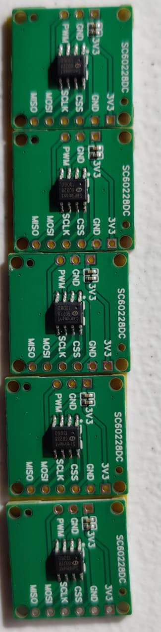
More details. I’m testing a second sensor (the first is buried inside a complex mechanical part, so I may have messed up the wiring or mechanically damaged the sensor). The PWM interface works fine. I’m proceeding to testing the SPI. It may be the sensor works fine but the code cannot “talk” to the sensor SPI, because the fact that the PWM works fine means the sensor is alive and signaling the angle.
Let me try with other means of connecting the wires.
Update1: The PWM frequency is 1kHz and duty cycle is between 0 and 100 depending on magnet orientation. This means realistically for PWM interface the RPM measured cannot exceed 600rpm (10rps) which will give 100 measuring points around the circle before we exceed the delay). That’s a little disappointing, they could have done easily 10kHz PWM.
Wow that’s brave. Hopefully the sensor will work on your board. Are you using the PWM or SPI interface?
Gives 0.0 reading. This is the code below. Let me see if I could read raw values directly from the SPI bypassing SimpleFOC.
#include <SimpleFOC.h>
#include <SimpleFOCDrivers.h>
#include "encoders/sc60228/MagneticSensorSC60228.h"

BLDCMotor motor = BLDCMotor(1);

BLDCDriver6PWM driver = BLDCDriver6PWM(PA8, PB13, PA9, PB14, PA10, PB15, PB12);

MagneticSensorSC60228 sensorSC60228(PA4);

void setup() {

  sensorSC60228.init();

  driver.voltage_power_supply = 12;

  driver.pwm_frequency = 15000;

  driver.init();

  motor.linkDriver(&driver);

  motor.voltage_limit = 3;   // [V]
  motor.velocity_limit = 10; // [rad/s] cca 50rpm

  motor.controller = MotionControlType::velocity_openloop;

  motor.init();

  Serial.begin(115200);
  Serial.println("Motor ready!");
  Serial.println("Set target velocity [rad/s]");
  _delay(1000);
}

void loop() {

  _delay(100);
   Serial.println(sensorSC60228.getAngle());
  motor.move(2);
}
Hi,
Any information from a logic analyser or oscilloscope?
Is the clk frequency ok?
Have you the requested pullups?
Cheers!
Still working on this. If it doesn’t work from the first try, then it takes days to do hardware debugging. Hopefully we don’t have to involve logic analyzers.