I’m sure you will make it work! ![]()
You’ve got more faith in me than myself…
Hmmm… I’m really itching try mine now too, but I shall still have to be patient a few more days…
The clock is fine, and the MISO send data is fine. The MOSI response however is coming at really low 200mV signal. I’m not sure what causes this. I can clearly see the MOSI on the oscilloscope however the MCU obviously cannot interpret signal that low. Therefore, it just reads 0.00.
The other thing I’m observing is that I cannot change the frequency. I’m using STM32F103. I tried different frequencies here:
SPI.beginTransaction(SPISettings(8000000, MSBFIRST, SPI_MODE1));
However it doesn’t seem to make any difference.
This is the raw code I’m running:
#include <SPI.h>

int CSSPin = PA4; // Pin CSS

const static uint16_t sendData = 0xAAAA; //Combing signal. Doesn't matter what we send;
uint16_t returnData;

void setup() {
  Serial.begin(115200);
  pinMode(CSSPin, OUTPUT);
  digitalWrite(CSSPin, HIGH);           //Master
  SPI.begin(CSSPin);                    // Setup SPI to use CSSPin

  PI.beginTransaction(SPISettings(8000000, MSBFIRST, SPI_MODE1));

  //SPI.setBitOrder(MSBFIRST);            // Most significant bit first
  //SPI.setDataMode(CSSPin,1);            // Use SPI Mode 1 (CPOL = 0, CPHA = 1)
  //SPI.setClockDivider(SPI_CLOCK_DIV2); // SPI.setClockDivider(CSSPin, 16);    // Set SPI Clock divider
}

void loop() {
  //digitalWrite(CSSPin, LOW);
  //delay(1);
  returnData = SPI.transfer16(CSSPin, sendData);
  //Serial.println(" Data: ");
  //Serial.println(returnData, HEX);
  //digitalWrite(CSSPin, HIGH);
  //delay(50);
}
Clock
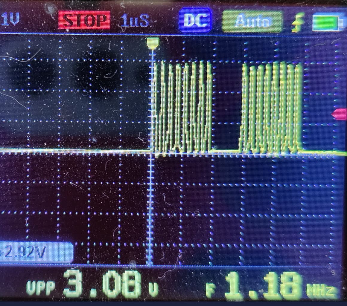
MISO, sending a binary comb signal (0xAAA)
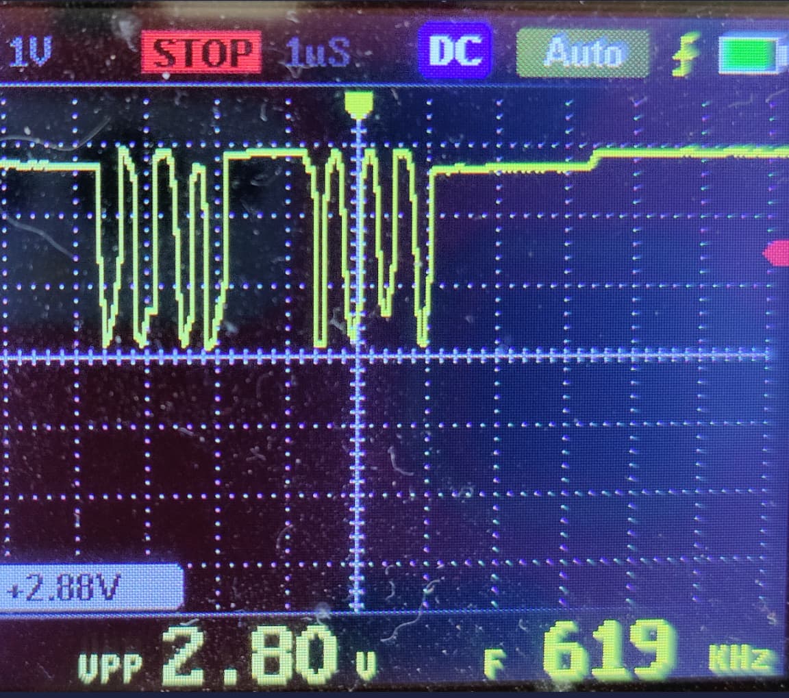
MOSI

Mystery…
If anyone has any ideas please let me know.

Hmmm… look at that. My documentation says 3v3, this one says 5V? Could it be that simple? 5V supply instead of 3V to get the SPI chip logic running? Let me check.
Where did you get this picture from, please?
Mine came from a Chinese datasheet manual.
This is the link of the datasheet
I’m would be surprised if 3.3V doesn’t work.
3v3 works fine for the PWM signal however perhaps SPI requires higher voltage to supply the tiny MCU that calculates the angle and runs the SPI logic? This is mystery Chinese stuff, so anything is possible. I’ll probably also have to burn some incense and pray to the ten gods to make it work.
Just to be sure. When you say MISO about 0xAAA, you meant MOSI right?
Let me check. There so many things that could have gone wrong.
Yes, I mistyped, it’s MOSI.
5V didn’t help, let me check the resistors. The chip PWM definitely works both on 3v and 5v, so that’s good to know. Keep digging.
OK I managed to burn the chip. Time to burn incense and sacrifice a small animal. BRB.
I’m checking other datasheet of the same series. Pullup on CLK and CS and pulldown on MOSI seems to be usually 10K et read frequency 1Mhz. Strange that you have absolutely no readings.

Maybe burn some components instead of animals, not sure that the god of chinese components understand otherwise… ![]()
I’ll check your answer tomorrow ![]()
BTW, in case you want to inspect other datasheet of the series, maybe some are more complex. And I don’t believe they have large differences.
Well, I used a datasheet from a different website. I’ve seen things in Chinese documentation that would chill your bones.
Have you made that chip work on your setup?
I believe that was the case, I had to sacrifice two of the chips. The third worked. I’ve no idea what the problem was however now I’m getting raw data with the code above. Let me continue with converting the raw data to angle. Stay tuned. Also, there was no need for pullups and pulldowns.
Edit: The raw sensor readings give values between 0 and 2^15. Looking at the documentation, and the way @runger had done it, we ignore the last bits so it seems correct so far. This is the exact code I used without pulls:
#include <SPI.h>

int CSSPin = PA4; // Pin CSS

const static uint16_t sendData = 0xAAAA; //Combing signal. Doesn't matter what we send;
uint16_t returnData;

void setup() {
  Serial.begin(115200);
  pinMode(CSSPin, OUTPUT);
  digitalWrite(CSSPin, HIGH);           //Master
  SPI.begin(CSSPin);                    // Setup SPI to use CSSPin

  SPI.beginTransaction(SPISettings(8000000, MSBFIRST, SPI_MODE1));

  //SPI.setBitOrder(MSBFIRST);            // Most significant bit first
  //SPI.setDataMode(CSSPin,1);            // Use SPI Mode 1 (CPOL = 0, CPHA = 1)
  //SPI.setClockDivider(SPI_CLOCK_DIV2); // SPI.setClockDivider(CSSPin, 16);    // Set SPI Clock divider
}

void loop() {
  digitalWrite(CSSPin, LOW);
  //delay(1);
  returnData = SPI.transfer16(CSSPin, sendData);
  Serial.print(" :: ");
  Serial.println(returnData, DEC);
  digitalWrite(CSSPin, HIGH);
  delay(300);
}
The code was executed on STM32F103
The dev branch code however didn’t work. This was the code I ran
// Open loop motor control example
#include <SimpleFOC.h>
#include <SimpleFOCDrivers.h>
#include "encoders/sc60228/MagneticSensorSC60228.h"

BLDCMotor motor = BLDCMotor(1);

BLDCDriver6PWM driver = BLDCDriver6PWM(PA8, PB13, PA9, PB14, PA10, PB15, PB12);

MagneticSensorSC60228 sensorSC60228(PA4);

void setup() {

  sensorSC60228.init();

  driver.voltage_power_supply = 12;

  driver.pwm_frequency = 15000;

  driver.init();

  motor.linkDriver(&driver);

  motor.voltage_limit = 3;   // [V]
  motor.velocity_limit = 10; // [rad/s] cca 50rpm

  motor.controller = MotionControlType::velocity_openloop;

  motor.init();

  Serial.begin(115200);
  Serial.println("Motor ready!");
  Serial.println("Set target velocity [rad/s]");
  _delay(1000);
}

void loop() {

  _delay(100);
  Serial.print(" :: ");
  Serial.println(sensorSC60228.getAngle());
  motor.move(2);
}
So the good news is that we have a working chip and raw SPI angle pull that pulls all 16 bits. It has to be fairly trivial to make the SimpleFOC angle code work. The dev branch code simply doesn’t read any angle, just gets stuck on one number. Let me try digging into it.
That seems like kind of good news! I wonder why the first two didn’t work?
The MOSI line should read 0, always, actually. The MISO line should carry the signal.
For the second code example, you have to add a:
sensorSC60228.update();
to the main loop. Otherwise the sensor value isn’t refreshed…
I’m not sure of the very first didn’t work because I tried with the dev code. After I confirm the code works I’ll plug back the first one because I didn’t want to touch it, its buried inside a very expensive planetary gear and I’m afraid to break anything.
The second plain stopped working after I ran it on 5V. It worked then it went silent.
sensorSC60228.update();
Let me try this now.
Yes it works. This is the main loop:
void loop() {
  _delay(100);
  Serial.print(" :: ");
  Serial.println(sensorSC60228.getAngle());
  sensorSC60228.update();
}
All right, so that’s really good news. Let me try plugging in the first sensor. It has a 1 meter cable so that could be another reason why I didn’t get a signal, perhaps the cable, even though I used very high quality TP, may be too much for the sensor to handle. Or the magnet is too far. So many things could go wrong. Stay tuned. It could just be I need to shorten the cable. Now I have something to compare against.
Excellent news, the dev code worked without any changes. Let me post a small example we could add to the codebase. I suck at git so you may copy/paste or write your own example.
Well, time to celebrate.
// Open loop motor control example
#include <SimpleFOC.h>
#include <SimpleFOCDrivers.h>
#include "encoders/sc60228/MagneticSensorSC60228.h"

BLDCMotor motor = BLDCMotor(1);

BLDCDriver6PWM driver = BLDCDriver6PWM(PA8, PB13, PA9, PB14, PA10, PB15, PB12);

MagneticSensorSC60228 sensorSC60228(PA4);

void setup() {

  sensorSC60228.init();

  driver.voltage_power_supply = 12;

  driver.pwm_frequency = 15000;

  driver.init();

  motor.linkDriver(&driver);

  motor.voltage_limit = 3;   // [V]
  motor.velocity_limit = 10; // [rad/s] cca 50rpm

  motor.controller = MotionControlType::velocity_openloop;

  motor.init();

  Serial.begin(115200);
  Serial.println("Motor ready!");
  _delay(1000);
}

void loop() {

  _delay(10);
  Serial.print(">> ");
  Serial.println(sensorSC60228.getAngle());
  sensorSC60228.update();
  motor.move(2);
}
Of course the real test would be using it in a closed loop but I’m too burned out. Tomorrow is another day.
@runger, thank you, excellent job. Also, thanks to @robotsmith for the document and suggestions.
Cheers,
Valentine
Hi!
Congrats! Very cool!
Not sure I was really helping ![]() but I was emotionally here
but I was emotionally here ![]()
Did you test it on a real setup with a motor? Do you think it is worth it?
Cheers!
I have some very busy family stuff now but will when I get the time