Hi all,
I have recently bought a DJI Mavic Mini, played with the SDK, created my own App, interfaced a Microsoft Sidewinder force feedback joystick to it…
And finally jumped to the idea to create a force feedback steering wheel to play with…
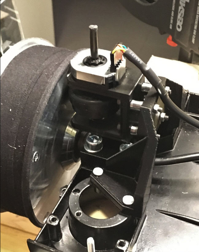
So today I acquired an old hoverboard and extracted the motor, which is really nice !
I know that this is not a simple project… Il will have to find a way to implement a Forcefeedback controller (PC side) and then to decode the “force commands” sent by the PC to feed them to SimpleFoc library to implement “force effects”. I do believe that starting by Foc torque control would be fine ?
I still have a lot of questions regarding the hardware side:
what kind of driver should I use ? Vesc ? B-G431B-ESC ? (many DIY ffb Wheels use these devices)
a custom made board (how hard is it to build one for this kind of motor ?)
Any advice or guideline would be apreciated !
Thanks
JP
Hey, I’m building a force feedback joystick with hoverboard motors.
For the driver I had a odrive that let the magic smoke out. Now I’m in the process off building a custom board. Probably with this igbt https://www.mouser.de/datasheet/2/308/1/FNB43060T2_D-2313697.pdf it’s a bit overkill but whatever it’s only 15$.
For the ffb interface I’m using a Arduino Leonardo with this on it GitHub - jmriego/Fino: An Arduino Joystick Library With Force Feedback Feature, the guy over there is pretty responsive, already has a issue opened to support wheels, if you reply to him in there, and tell him that you are interested in support for steering wheels he probably will implement it.
Hoverboard motors with voltage/torque controll are pretty good for ffb because the seam to have very low cogging torque and are about 10Nm of torque.
If you have more questions or are interested in my driver board development, just ask me.
Many people have used the B-G431B-ESC, the price is good - but it is very compact and can be hard to use…
Making your own board is certainly possible, and a cool project - personally, I certainly like designing these boards - but it does take some time and effort, so it would be more like its own project, I think… I would not see it as being on the direct path to making a steering wheel - more like a major detour…
I also used the g431b-esc and a good solution I found for the small solder pads, was to use some molex 2510 PCB mount connectors and bend the outer pins to the inside and solder them in a 45° angel to the solder pads. Unfortunately I don’t have a picture of it at the moment.
I will have a look at the Arduino Leonardo controler. Curently I am struggling with a a PIC 18F4550 driver… almost working but not properly recognized by “forcetest.exe” : PIC18F4550
I am definitively interested in your IGBT driver. If I can help it will be with pleasure. I can easily make single sided PCBs. Don’t hesitate !
A rubber roller is “rolling” on the motor hub. Seems very easy to reproduce, the roller can even be printed using TPU for a good smoothness and adhesion to the wheel.
The question that I have is if simplefoc will cope with multiple rotations of the encoder for a single turn of the motor shaft ?
I mean that if I use a 4096 values magnetic encoder, and as it is an absolute encoder, I will get N zero resets after each turn. Does simplefoc handle this ?
No it currently doesn’t handle this. On the one hand I don’t think the adaptation would be such a problem because SimpleFOC cares about electrical angle primarily for the commutation, and there are many electrical revolutions per full turn.
However I think you gave a different problem. For the electrical revolutions the physical Setup of how a motor works guarantees that there is always an integer number of electrical revolutions per full turn. For your setup, what guarantees this? Even if the rubber wheel size is chosen to be an integer multiple of the shaft circumference, it won’t be that precise, and you‘ll have small amounts of slip, meaning you’d lose the motors electrical zero… over Time the errors will add up and the commutation will become increasingly inefficient and eventually stop working.
There was another thread recently discussing a similar idea, and the consensus there was also that it’s not a good idea to separate the FOC sensor from the motor shaft…
I think it would work if you just multiply the reduction ratio with the 4096, so if you have a reduction of 1 to 6.6 you just multiply 4096 times 6.6.
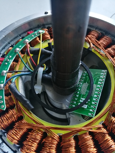
In this setup I would worry about the rubber wheel slipping. I disassembled the motor and in the housing with the magnets I drilled a hole trough the middle off the housing where the bearing is, now you can mount a magnet to the shaft and attach the encoder to the housing.
What he is talking about on the odrive Forum isn’t about accuracy, it’s about the index pulses, Wich aren’t really that important if you calibrate the wheel on startup.