Wiring AS5048A Magnetic Sensor to RP2040

Hey Everyone.

I recently bought a GM3506 Gimbal Motor with a AS5048A magnetic sensor attached and I got it to work on an arduino uno. I had to switch the AS5048A cable from the 3 wire to the 6 wire to get it to work and connected it to the arduino as seen in the image below.

The code I used to connect the AS5048A to the arduino was the following:

MagneticSensorSPI sensor = MagneticSensorSPI(AS5048_SPI, 10);

This all worked great by for my project I don’t actually want to use a Arduino nano I trying to use a RP2040 which is naturally connected to a display (Waveshare RP2040 MCU Board, With 1.28inch Round LCD).

The pins on this RP2040 can be seen below but Im struggling to see how to change the wire connections from the Uno to the RP2040 cause to connect to the Arduino i had to use the SCK, CIPO, COPI, and SS ports. Which ports do i need to connect to on the RP2040 to get the magnetic sensor to work? Does the code from above work on a RP2040 as well?

Yes, you can certainly use this sensor with the RP2040. The RP2040 supports SPI.

The “standard” Pico has this pinout:

You can see which pins are used by the SPI interfaces in the pink boxes. So looking at the pinout of your board, it does look like GPIOs 2,3,4,5 (for SPI0) are available on the header, and also not used by the on-board peripherals.

So you could try pins 2 (SCK), 3 (MOSI/COPI), 4 (MISO/CIPO), 5 (nCS - you can also use any other pin for this).

Hm I’ve tried connected the wire to a pi Pico as follows

I couldn’t get the encoder to run on the same code that worked on the Uno.

#include <SimpleFOC.h>

// MagneticSensorSPI(MagneticSensorSPIConfig_s config, int cs)
//  config  - SPI config
//  cs      - SPI chip select pin 
// magnetic sensor instance - SPI
MagneticSensorSPI sensor = MagneticSensorSPI(AS5048_SPI, 10);
// alternative constructor (chipselsect, bit_resolution, angle_read_register, )
// MagneticSensorSPI sensor = MagneticSensorSPI(5, 14, 0x3FFF);

void setup() {
  // monitoring port
  Serial.begin(115200);

  // initialise magnetic sensor hardware
  sensor.init();

  Serial.println("Sensor ready");
  _delay(1000);
}

void loop() {
  // iterative function updating the sensor internal variables
  // it is usually called in motor.loopFOC()
  // this function reads the sensor hardware and 
  // has to be called before getAngle nad getVelocity
  sensor.update();
  // display the angle and the angular velocity to the terminal
  Serial.print(sensor.getAngle());
  Serial.print("\t");
  Serial.println(sensor.getVelocity());
}

I tried
MagneticSensorSPI sensor = MagneticSensorSPI(AS5048_SPI, 10);
MagneticSensorSPI sensor = MagneticSensorSPI(5, 14, 0x3FFF);
MagneticSensorSPI sensor = MagneticSensorSPI(7, 14, 0x3FFF);

but all i kept on getting was 0 values in the Arduino IDE serial port terminal. Any idea whether its a wiring/hardware issue or whether there’s something I should change in my code? many thanks for the help so far

Is it an issue if 3.3V vs 5V power? Picos like 3.3V while UNOs use 5V…

The sensor has a different configuration depending on which you want to use…

@FinderSiri I have to same motor and AS5048A Sensor. But I only got the 3 pin cable version.
Do I need to get a 6pin JST SC or 8pin cable that will fit into the sensor?

Hi @Mike_Braun , welcome to SimpleFOC!

I believe you can solder a 6-pin connector (the outer 2 pins are for the connector’s mounting pins) to the other side of the sensor, or you can directly solder wires to it - that will be fussy soldering unfortunately.

If the the sensor already has a connector (I’m not sure which model you have exactly) then you just need a matching cable - probably 6-pin JST-SH 1.0 type.

If the forum lets you, you could post a picture of your version of the sensor…

Hello @runger
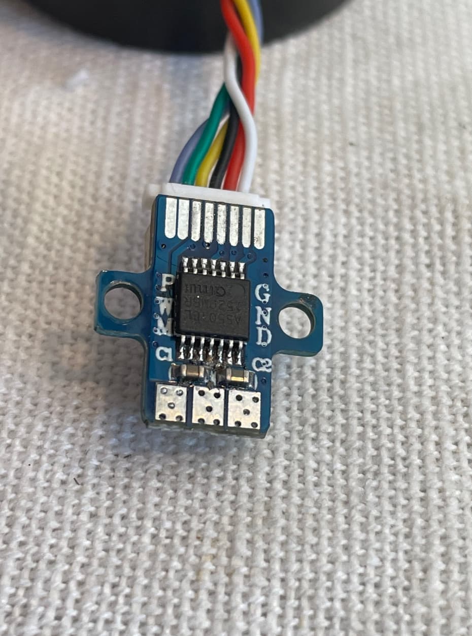
Thank you very much for your help and feedback. I had a look at the Encoder and it’s the same one as FinderSiri posted. And I found the cable :slight_smile: My bad!!

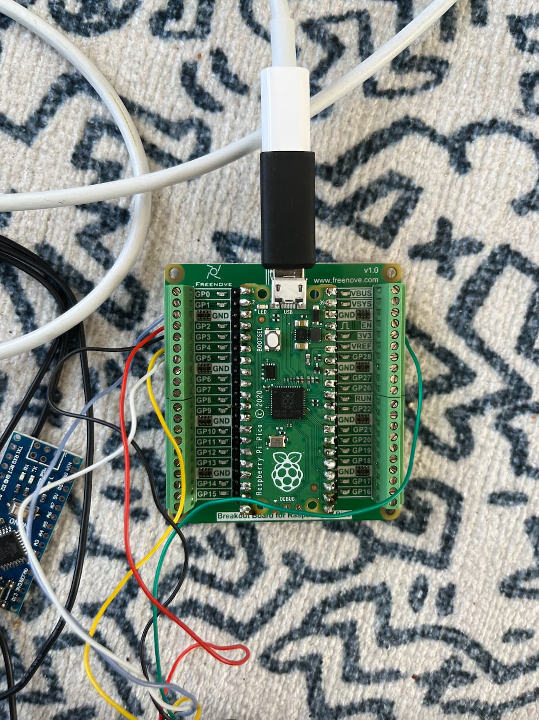
But im still stuck that the motor in not turning.

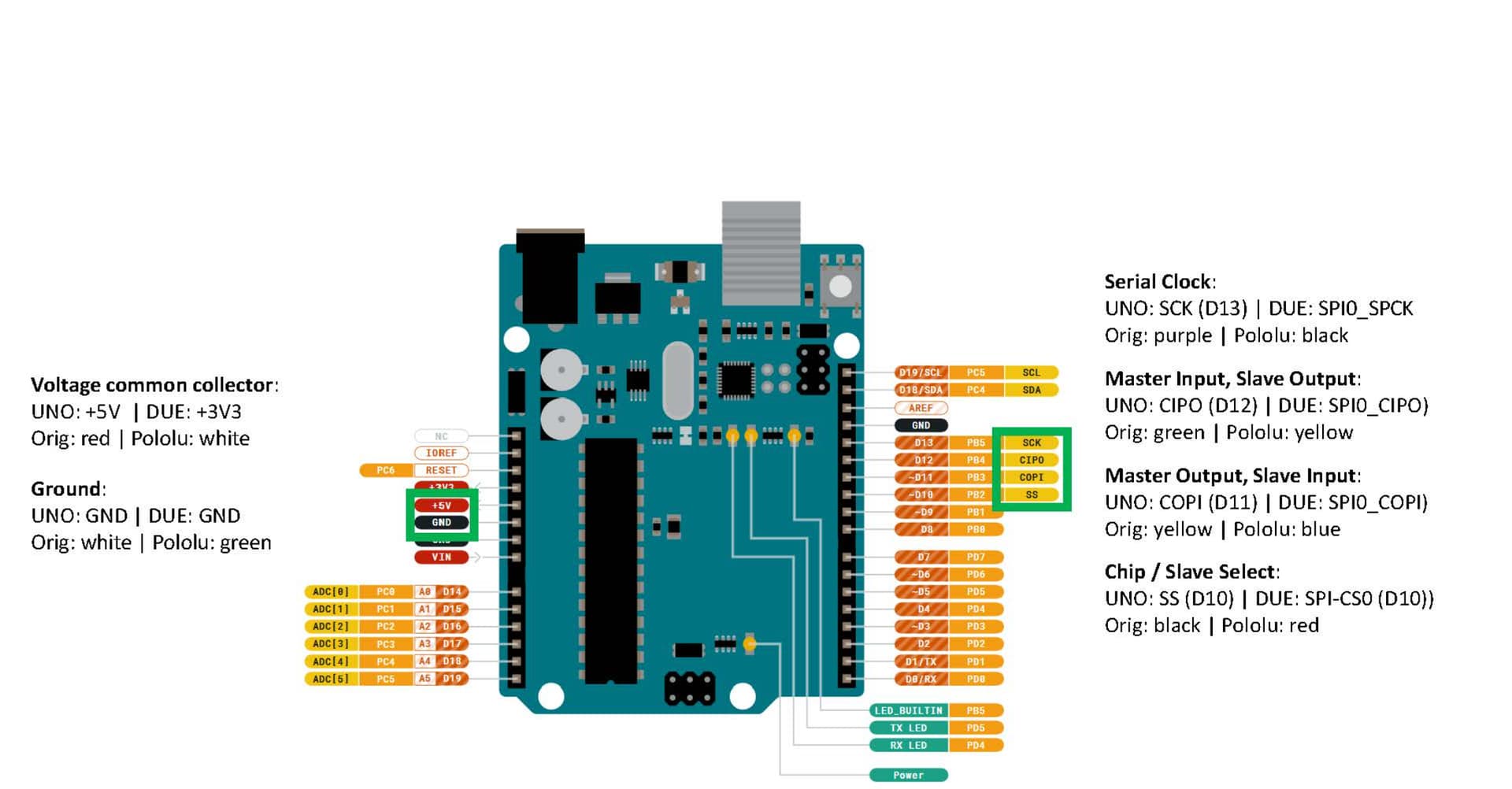
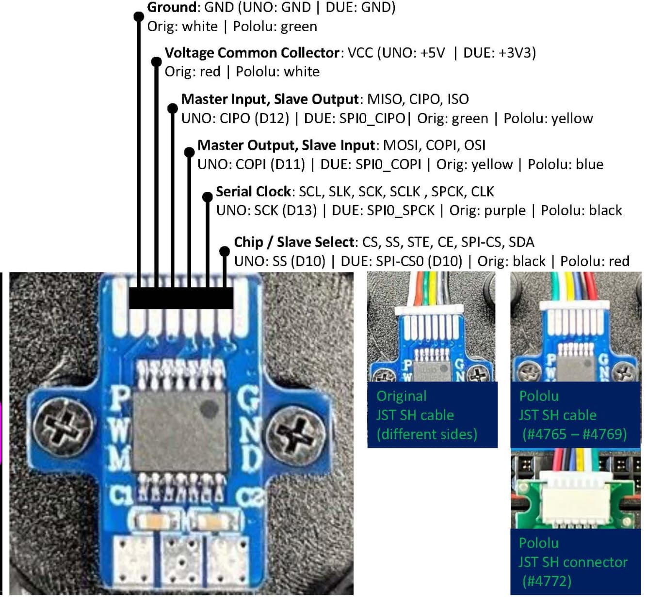
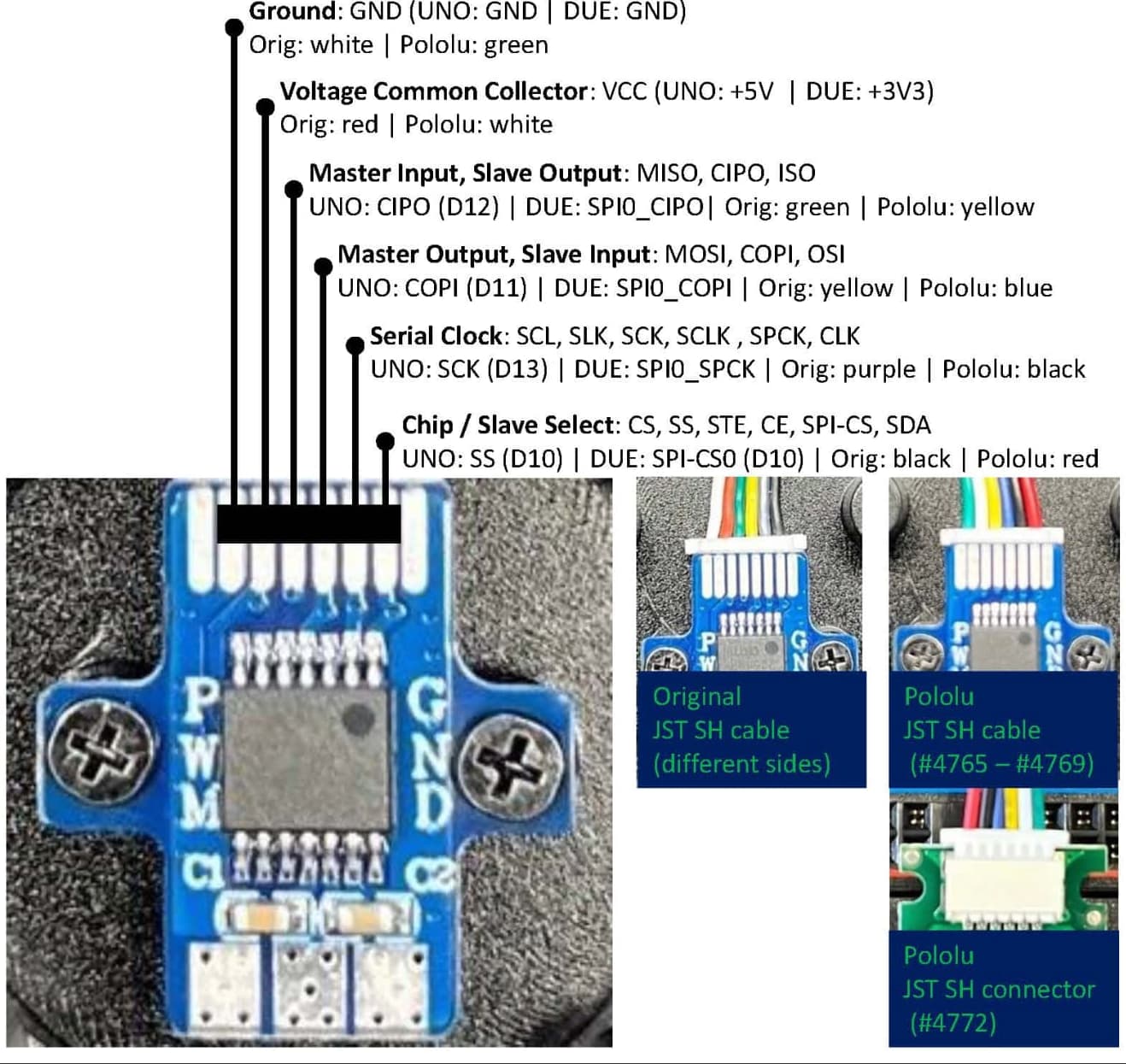
I did the same wiring as this Image, the ORG version.

@runger could you please have a look at my code? Maybe im too blond or don’t understand what im missing. Thanks!!!

#include “Arduino.h”
#include “Wire.h”
#include “SPI.h”
#include “SimpleFOC.h”
#include “SimpleFOCDrivers.h”
#include “encoders/as5048a/MagneticSensorAS5048A.h”

// init BLDC motor
BLDCMotor motor = BLDCMotor(9, 5.8);
// init driver
BLDCDriver3PWM driver = BLDCDriver3PWM(9, 8, 7, 6);
// init encoder
#define SENSOR1_CS 10 // some digital pin that you’re using as the nCS pin
MagneticSensorAS5048A sensor1(SENSOR1_CS);
// angle set point variable
float target_angle = 0;
// commander interface
Commander command = Commander(Serial);
void onTarget(char* cmd){ command.scalar(&target_angle, cmd); }

void setup() {

// initialize magnetic sensor hardware
sensor1.init();

// power supply voltage
// default 12V
driver.voltage_power_supply = 12;
driver.init();
//pinMode(7,OUTPUT); // declares pin 12 as output and sets it to LOW
// link the motor to the driver
motor.linkDriver(&driver);

// set control loop to be used
motor.controller = MotionControlType::angle;

// controller configuration based on the control type
// velocity PI controller parameters
// default P=0.5 I = 10
motor.PID_velocity.P = 0.2;
motor.PID_velocity.I = 20;
// jerk control using voltage voltage ramp
// default value is 300 volts per sec ~ 0.3V per millisecond
motor.PID_velocity.output_ramp = 1000;

//default voltage_power_supply
motor.voltage_limit = 12;

// velocity low pass filtering
// default 5ms - try different values to see what is the best.
// the lower the less filtered
motor.LPF_velocity.Tf = 0.01;

// angle P controller
// default P=20
motor.P_angle.P = 20;
// maximal velocity of the position control
// default 20
motor.velocity_limit = 4;

// initialize motor
motor.init();
// align encoder and start FOC
motor.initFOC();

// add target command T
command.add(‘T’, onTarget, “target angle”);

// monitoring port
Serial.begin(115200);
Serial.println(“Motor ready.”);
Serial.println(“Set the target angle using serial terminal:”);
_delay(1000);
}

void loop() {
// iterative FOC function
motor.loopFOC();

// function calculating the outer position loop and setting the target position
motor.move(target_angle);

// user communication
command.run();
}

Hey, have you found the problem?

You initialize the motor with 9 pole pairs - are you sure it’s right? It’s an uncommon number of pole pairs. The I-Term on your velocity seems a little high.

You’re running the motor in angle mode in this code. Have you made sure it works well in the simpler modes first?

  • first it would be good to just check the sensor is working, with the motor not powered at all. Print the sensor values and make sure it returns ±6.28 (radians) for a full turn of the motor.

  • then you can try open loop mode to make sure the motor works well without the sensor

  • then torque-voltage mode is the next test, using motor and sensor in combination, but not requiring any PID tuning

  • after this, tuning the velocity PID and making sure velocity mode is working well

  • and finally, angle mode, which uses all the other modes above as part of its function…

Hello @runger

Thank you very much for your Feedback. Yes the pole pairs are wrong and I did change it to 11. I had a bit of a miss understanding :slight_smile:

After doing lots of reading and testing, the motor plus encoder is running on my Arduino Nano ESP32.
I did post a new problem, but it is a user c++ problem whahaha

Maybe you have time to give me an idea how I can do this?

Maybe you could let me know what the command is to move the motor, like T2
But in code?! That part I still don’t understand.

Thanks for your Help!!

1 Like