CCTV Gimbal Motor Project

Hello C++ Experts

It took me a few days to get my setup working with the example files. But the setup is done.
Im using one iPower Motor GM3506 with AS5048 encoder on a Arduino Nano ESP32 and SimpleFOC Mini. With one 12V power supply for the Arduino and FOC mini.

Pins in the sketch are mixed mode. SPI and Motor EN pin are configured as Arduino pins and IN1, 2 and 3 as ESP32 GPIO Pins.

I will 3D Print a mount for the motor and a mount for the webcam to the motor.

But my problem is C++ :frowning: I can make a LED blink on the Arduino, that’s about is. :frowning:
And that is where I need help please!!!

I think the angle Sketch works the best for what I would like to do.

Step 1. Get the motor to move 270 degrees in a loop, so move from 0 135 degrees then -135 degrees and back 135 degrees ec.
It will have to move slow, so that the webcam can pickup the image, but I would like to have maximum torque on the motor. Can anyone please help me with this if and if then if whahahaha

Step 2. But this has no prior, I would like to add Bluetooth and be able to change the angle and speed of the motor movement, without having to take it down and load new code.

My sketch im testing with at the moment.

#include <SimpleFOC.h>

// magnetic sensor instance - SPI
MagneticSensorSPI sensor = MagneticSensorSPI(AS5048_SPI, 10); //(CS - Arduino Port)

// BLDCMotor(pole pair number, phase resistance [Ohms], KV rating [rpm/V])
BLDCMotor motor = BLDCMotor(11); //5.8ohm
BLDCDriver3PWM driver = BLDCDriver3PWM(18, 8, 9, 8); //(IN1 - GPIO Port, IN2 - GPIO Port, IN3 - GPIO Port, EN - Arduino Port)


// angle set point variable
float target_angle = 0;
// instantiate the commander
Commander command = Commander(Serial);
void doTarget(char* cmd) { command.scalar(&target_angle, cmd); }

void setup() {

  // initialise magnetic sensor hardware
  sensor.init();
  // link the motor to the sensor
  motor.linkSensor(&sensor);

  // driver config
  // power supply voltage [V]
  driver.voltage_power_supply = 12;
  driver.init();
  // link the motor and the driver
  motor.linkDriver(&driver);

  // choose FOC modulation (optional)
  motor.foc_modulation = FOCModulationType::SpaceVectorPWM;

  // set motion control loop to be used
  motor.controller = MotionControlType::angle;

  // contoller configuration
  // default parameters in defaults.h

  // velocity PI controller parameters
  motor.PID_velocity.P = 0.2f;
  motor.PID_velocity.I = 20;
  motor.PID_velocity.D = 0;
  // maximal voltage to be set to the motor
  motor.voltage_limit = 6;

  // velocity low pass filtering time constant
  // the lower the less filtered
  motor.LPF_velocity.Tf = 0.01f;

  // angle P controller
  motor.P_angle.P = 20;
  // maximal velocity of the position control
  motor.velocity_limit = 2;

  // use monitoring with serial
  Serial.begin(115200);
  // comment out if not needed
  motor.useMonitoring(Serial);


  // initialize motor
  motor.init();
  // align sensor and start FOC
  motor.initFOC();

  // add target command T
  command.add('T', doTarget, "target angle");

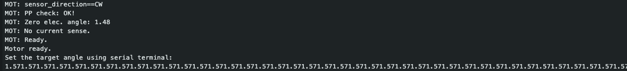
  Serial.println(F("Motor ready."));
  Serial.println(F("Set the target angle using serial terminal:"));
  _delay(1000);
}


void loop() {

  // main FOC algorithm function
  // the faster you run this function the better
  // Arduino UNO loop  ~1kHz
  // Bluepill loop ~10kHz
  motor.loopFOC();

  // Motion control function
  // velocity, position or voltage (defined in motor.controller)
  // this function can be run at much lower frequency than loopFOC() function
  // You can also use motor.move() and set the motor.target in the code
  motor.move(target_angle);


  // function intended to be used with serial plotter to monitor motor variables
  // significantly slowing the execution down!!!!
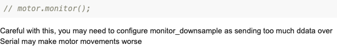
  // motor.monitor();

  // user communication
  command.run();
}

Im thankful for any help or feedback!

Hey,

There are several approaches you can take for this. I’ll highlight two:

  1. Since you’re on ESP32, you have the FreeRTOS library available as part of the framework. With this you can create multiple tasks which run in “parallel”, so you could have one for the motor, one to adjust the target over time, and one to take new commands from bluetooth.
    The thing is that using FreeRTOS is a bit complicated, and might not be the best choice if you’re not (yet!) so solid in C++.

  2. Ignoring bluetooth for now, to make the target value change over time without something like FreeRTOS to make it a seperate task, you need another control loop that is somehow part of your main loop. That new control loop adjusts the target value over time. A simple approach can be this:

  • add a timestamp to your global variables. Initialize it with the current time at the end of the setup() function
  • each time through the main loop, compare the timestamp to the current time. If the difference is >100, then 100ms have passed, and its time for your new control loop to adjust the target
  • adjust the target by a given amount, lets call it the “step”

Something like this:

#define INTERVAL 100     // 100ms
#define STEPSIZE  0.05   // radians
#define ENDANGLE (_2PI * 0.75)
#define STARTANGLE (_2PI * 0.25)

unsigned long timestamp;
int direction = 1;   // 1 is forwards, -1 is backwards


void setup(){
  ...
  timestamp = millis();
}


void loop(){
   ...
   unsigned long now = mills();
   if (timestamp > INTERVAL) {
      target_angle = target_angle + (STEPSIZE * direction);
      if (target_angle > ENDANGLE) {
         target_angle = ENDANGLE;
         direction = -1;
      }
      if (target_angle < STARTANGLE) {
         target_angle = STARTANGLE;
         direction = 1;
      }
      timestamp = now;
   }
}
1 Like

Hello @runger

Thank you very much for your Feedback and help!

image
Good that it is weekend soon :wink: so I can do some reading. Sounds very interesting.

I added your code so that I can test and understand it better but im getting this error:
Compilation error: ‘target’ was not declared in this scope.

Must I define the target?

image

#include <SimpleFOC.h>
// magnetic sensor instance - SPI
MagneticSensorSPI sensor = MagneticSensorSPI(AS5048_SPI, 10); //(CS - Arduino Port)

// BLDCMotor(pole pair number, phase resistance [Ohms], KV rating [rpm/V])
BLDCMotor motor = BLDCMotor(11); //5.8ohm
BLDCDriver3PWM driver = BLDCDriver3PWM(18, 8, 9, 8); //(IN1 - GPIO Port, IN2 - GPIO Port, IN3 - GPIO Port, EN - Arduino Port)

// angle set point variable
float target_angle = 0;

// instantiate the commander
Commander command = Commander(Serial);
void doTarget(char* cmd) { command.scalar(&target_angle, cmd); }

//***************************************
#define INTERVAL 100 // 100ms
#define STEPSIZE 0.05 // radians
#define ENDANGLE (_2PI * 0.75)
#define STARTANGLE (_2PI * 0.25)

unsigned long timestamp;
int direction = 1; // 1 is forwards, -1 is backwards
//***************************************

void setup() {
// initialise magnetic sensor hardware
sensor.init();
// link the motor to the sensor
motor.linkSensor(&sensor);

// driver config
// power supply voltage [V]
driver.voltage_power_supply = 12;
driver.init();
// link the motor and the driver
motor.linkDriver(&driver);

// choose FOC modulation (optional)
motor.foc_modulation = FOCModulationType::SpaceVectorPWM;

// set motion control loop to be used
motor.controller = MotionControlType::angle;

// contoller configuration
// default parameters in defaults.h

// velocity PI controller parameters
motor.PID_velocity.P = 0.2f;
motor.PID_velocity.I = 20;
motor.PID_velocity.D = 0;
// maximal voltage to be set to the motor
motor.voltage_limit = 6;

// velocity low pass filtering time constant
// the lower the less filtered
motor.LPF_velocity.Tf = 0.01f;

// angle P controller
motor.P_angle.P = 20;
// maximal velocity of the position control
motor.velocity_limit = 2;

// use monitoring with serial
Serial.begin(115200);
// comment out if not needed
motor.useMonitoring(Serial);

// initialize motor
motor.init();
// align sensor and start FOC
motor.initFOC();

// add target command T
command.add(‘T’, doTarget, “target angle”);

Serial.println(F(“Motor ready.”));
Serial.println(F(“Set the target angle using serial terminal:”));
_delay(1000);

//***************************************
timestamp = millis();
//***************************************

}

void loop() {
// main FOC algorithm function
// the faster you run this function the better
// Arduino UNO loop ~1kHz
// Bluepill loop ~10kHz
motor.loopFOC();

// Motion control function
// velocity, position or voltage (defined in motor.controller)
// this function can be run at much lower frequency than loopFOC() function
// You can also use motor.move() and set the motor.target in the code
motor.move(target_angle);

// function intended to be used with serial plotter to monitor motor variables
// significantly slowing the execution down!!!
// motor.monitor();

// user communication
command.run();

//***************************************
unsigned long now = millis();
if (timestamp > INTERVAL) {
target_angle = target_angle + (STEPSIZE * direction);
if (target_angle > ENDANGLE) {
target = ENDANGLE;
direction = -1;
}
if (target_angle < STARTANGLE) {
target_angle = STARTANGLE;
direction = 1;
}
timestamp = now;
}
}

Thanks again for your help!!

oops - should be “target_angle”

This was just an example, I didn’t try to compile it… sorry about that!

No problem. :slight_smile:

Some feedback.
When I run
unsigned long now = millis();
if (timestamp > INTERVAL) {
target_angle = target_angle + (STEPSIZE * direction);
if (target_angle > ENDANGLE) {
target_angle = ENDANGLE;
direction = -1;
}
if (target_angle < STARTANGLE) {
target_angle = STARTANGLE;
direction = 1;
}
timestamp = now;
}
}

The motor goes into vibration mode. Not moving at all, only vibrating.

If I run only

unsigned long now = millis();
if (timestamp > INTERVAL) {
target_angle = target_angle + (STEPSIZE * direction);
if (target_angle > ENDANGLE) {
target_angle = ENDANGLE;
direction = -1;
Serial.print(ENDANGLE);
}
//if (target_angle < STARTANGLE) {
// target_angle = STARTANGLE;
// direction = 1;
//}
timestamp = now;
}

The motor moves in one direction, but never stops.

MOT: sensor_direction==CW

MOT: PP check: OK!

MOT: Zero elec. angle: 1.54

MOT: No current sense.

MOT: Ready.

Motor ready.

Set the target angle using serial terminal:

4.71

Is there maybe a way to get the angle and not work with target_angle? Just thinking loud :wink:

Looks like a bug, target angle will never be set to start angle. Try:

unsigned long now = millis();
if (timestamp > INTERVAL) {
target_angle = target_angle + (STEPSIZE * direction);
if (target_angle > ENDANGLE) {
target_angle = STARTANGLE;
direction = -1;
}
if (target_angle < STARTANGLE) {
target_angle = ENDANGLE;
direction = 1;
}
timestamp = now;
}
}

If you want to see your current angle, unconnected this line

// motor.monitor();

Careful with this, you may need to configure monitor_downsample as sending too much ddata over Serial may make motor movements worse

Hello Owen

Thanks for your feedback and code update.
I did test ist, but get no movement on the motor after the encoder zero point.

image

If I Serial.print(ENDANGLE); I see the angle is some super loop and the Arduino is also reacting bad for new sketches.

image

I will check the documentation before, so that I understand it better. I did activate it yesterday and I could see how the angle get bigger and bigger.

That version with Owen’s correction actually looks good to me now… that should work. You can play with the interval and step size to make the motion nicer, and of course you can always get more complicated - the sudden change in direction isn’t so nice for example, with some effort you can add accelleration and deceleration to the loop, etc…

Hello @runger & @Owen_Williams

I did test the code that @Owen_Williams send me and unfortunately its not working.
What I could find out, is that if the code sets the target_angle, it doest wait for the motor to arrive at the target_angel. So out of the code it will only do the last past.

image

It s like you give the command T20 and then T0. The motor doest first do to T20 and then T0, but would just start turning to go back to T0.

Is there a way maybe to add motor.shaft_angle to the code. I did try a few things, but did not get it right.
Like this if the code sends a target_angle, it has to wait or first query the motor.shaft_angle before it will move on to the next if in the code.

Thank you for your help and support!!!

Yes, you’re right, seems neither Owen nor I saw this mistake. How about this?

unsigned long now = millis();
if (timestamp > INTERVAL) {
  target_angle = target_angle + (STEPSIZE * direction);
  if (motor.shaft_angle > ENDANGLE) {
    direction = -1;
  }
  if (motor.shaft_angle < STARTANGLE) {
    direction = 1;
  }
  timestamp = now;
}
1 Like

Thank you very very much @runger

You make it look so easy! But the good thing is it’s working! You awesome!!

I did not understand this part of the code.
target_angle = target_angle + (STEPSIZE * direction);

But looking at the Serial Print you just sending the motor in that direction and once the motor shaft angle is trigger it changes direction :slight_smile: Very clever!!

Target Abgle: -3186.73
ENDANGLE: 4.71
STARTANGLE: 1.57
Target Abgle: -4188.36
ENDANGLE: 4.71
STARTANGLE: 1.57
Target Abgle: -5185.55
ENDANGLE: 4.71
STARTANGLE: 1.57
Target Abgle: -6182.64
ENDANGLE: 4.71
STARTANGLE: 1.57

Thanks again for your help!!

1 Like

In fact there is still a mistake though… :frowning: the interval isn’t being used correctly, the loop will just run at max speed…

This version checks the difference between now and the timestamp against the interval, that should be better. With this version if you play with the values of STEPSIZE and INTERVAL you should be able to set the speed you want.

unsigned long now = millis();
if ((now - timestamp) > INTERVAL) {
  target_angle = target_angle + (STEPSIZE * direction);
  if (motor.shaft_angle > ENDANGLE) {
    direction = -1;
  }
  if (motor.shaft_angle < STARTANGLE) {
    direction = 1;
  }
  timestamp = now;
}

Hello @runger

Thank you for the updated code. I got the motor to move the way I would like it to.
With max V and getting max power.

But what I still don’t understand is how I can make it move slower without reducing the motor voltage?

Can you please help me and tell me if I need to change it hier?

// Velocity PI controller parameters
motor.PID_velocity.P = 0.2f;
motor.PID_velocity.I = 20;
motor.PID_velocity.D = 0;
// Maximal voltage to be set to the motor

Or

// Velocity low pass filtering time constant
// The lower the less filtered
motor.LPF_velocity.Tf = 0.01f;

// Angle P controller
motor.P_angle.P = 20;
// Maximal velocity of the position control
motor.velocity_limit = 2;

Or ???

Thank you very much for your support!!!

You should just be able to set this, probably shrink stepsize. I guess you could also limit the output of PID but this does not seem like a very clean solution.