come on! ![]() … why I’m trying to use simplefoc lib?…
… why I’m trying to use simplefoc lib?…
because I’m bamby in C++ and BLDC motor.. !
am I looking for something that doesn’t exist?
come on! ![]() … why I’m trying to use simplefoc lib?…
… why I’m trying to use simplefoc lib?…
because I’m bamby in C++ and BLDC motor.. !
am I looking for something that doesn’t exist?
Yeah, if you don’t want to learn C++, you should probably buy an ODrive or something instead of trying to reuse the onewheel motherboard. SimpleFOC is a huge boost compared to starting from scratch, but it’s still fairly technical compared to a well tested and documented firmware written for a specific piece of hardware. And even those are difficult to use. When I tried ODrive, I ended up having to add an arduino and its associated rat’s nest of wires just to tell the motor to relax when set to 0 speed.
Of all things I’ve done in life, I think brushless motor control has the largest gap between how complicated I imagined it to be and how complicated it really is.
On the bright side, SimpleFOC uses C++ in the old fashioned “C with classes” style. I can’t stand “modern C++” with its ridiculously complicated standard library that you’re pressured into using for absolutely everything. I’m happiest with regular C, but the addition of member functions and inheritance does save a fair amount of typing, so I begrudgingly admit it’s the better choice in most cases.
none of that sir…. to be clear, I don’t emit a single critic about the actual lib… a gift for community.
my only concern is to know if simplefoc is able to generate waves to drive a motor quietly. if yes , I will dig further, if no , okay , no pb either, I’ll push my investigation for my personnal fun
best regards
Certainly it can. And since calling setPwm directly works, the problem is pretty much narrowed down to something that happens in the very small BLDCMotor::velocityOpenloop function, so it should be easy to find. And hopefully fixing it will fix the bad closed loop waveforms too.
okay… “je vais tirer la pelotte”
This is really weird. The output from open loop should be a nice sine wave, like the one you posted from your own test code.
Can you set an appropriate voltage limit and then run the motor in pure voltage mode, without setting the Resistance, KV or inductance values on the motor?
This should remove any complicated calculations based on the sensor that might affect the results…
I would really love to had make a mistake.
I will try tomorrow….
Hi
after removing all the bellow stuff …
//BLDCMotor motor = BLDCMotor(polePairs,0.25,1.00,0.006);
BLDCMotor motor = BLDCMotor(polePairs);
the result is exactly the same..
but
if I remove the line
motor.monitor();
il the main loop ,
void loop()
{

//________normal section
  // main FOC algorithm function
  motor.loopFOC();
  // Motion control function
  motor.move();
   // display the currents
 // motor.monitor();
//________end normal section

}
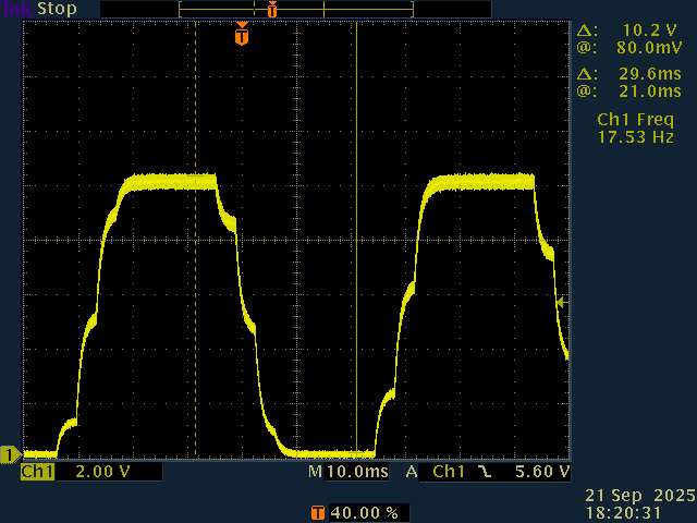
I have the following curve ::
so behaviour change only by removing motor monitoring??? ![]()
still not sinus … but.. it is probably a clue for you guys….
You know, I’ve never actually used the monitoring code… Looking at it now, it can indeed cause blocking delays. I think it was ok on the original 8-bit arduinos, but on STM32, multiple calls to Serial.print in a single frame is bad. We should change it to either print one variable per frame and divide the delay by the number of variables enabled, or have it print into a char array and then print the whole thing to serial at once.
The chopped peaks of the wave looks like it’s saturating. One more confusing thing about SimpleFOC is that the motor voltage limit can only be half the driver voltage limit (or 58% if using SpaceVectorPWM). I’m not sure if that’s what’s happening in this case, but it’s something to be aware of. Here’s an article explaining it in more detail Field Oriented Control | Arduino-FOC
so you are saying that I’m the first and only guy that used the monitoring feature , really? ![]()
herebellow the limits implemented :
// pwm frequency to be used [Hz]
  // for atmega328 fixed to 32kHz
  // esp32/stm32/teensy configurable
  driver.pwm_frequency = 15000;
  // power supply voltage [V]
  driver.voltage_power_supply = 20;
  // Max DC voltage allowed - default voltage_power_supply
  driver.voltage_limit = 10;
  // dead_zone [0,1] - default 0.02f - 2%
  driver.dead_zone = 0.01f;
I remember that I also tested the
driver.voltage_limit = 5;
just to see… and the result was a wave , indeed half the previous but divided by two … with the same shape.
tomorrow I’ll try to remove completly the
SimpleFOCDebug::enable(&SerialDebug);
bye and good night ![]()
I just noticed the voltage divisions set to 2 in the last oscilloscope image. So 10V peak to peak is indeed saturating at your driver voltage limit. Try motor.voltage_limit = 1; and see how it looks.
Also double check that your driver.voltage_power_supply is correct. Looking back at your successful sine wave in post #39, the oscilloscope divisions are 5V, so peak to peak amplitude is ~16V. But since the code says 10+4*sin(i) it should be 8V peak-to-peak. The voltages you pass to setPwm are divided by voltage_power_supply to give the raw PWM duty, so if voltage_power_supply doesn’t match the actual power supply, then the actual output voltages won’t match your commanded voltages either.
Indeed surprising I haven’t heard of anyone else having trouble with it. Although I doubt it’s been your primary problem since it’s unlikely the interruptions would be perfectly synchronized to your wave frequency to create the same wave shape every cycle.
things are turning interesting…
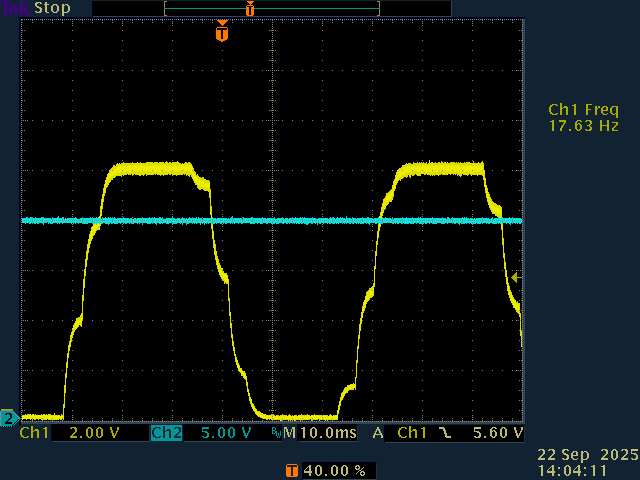
so first, I replay my last test .. : for your convinience I added the power input voltage in BLUE
as one can see, power voltage is 20V
now, as required , I added the following :
motor.voltage_limit=1;
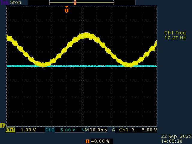
and … tada!
finally … a nice sinus… ![]() ok done! we got it!
ok done! we got it!
let’s back on the culprit… I uncommented the following :
motor.monitor(); <= sinewavekiller!
and guess what…
so… for my personnal understanding…
-I shouldn’t use “xxx.monitor” method anymore
-it is unclear to me the difference between :
driver.voltage_limit = 10;
and
motor.voltage_limit=1;
![]()
I think, I figured out my answer by my own.
driver.voltage_limit = 10;
allow PWM max duty cycle to stop at around 50% in my case, because
driver.voltage_power_supply = 20;
and
motor.voltage_limit=1;
set the max PWM seen for one phase vs gnd , here 1V meaning 2V peak to peak
right?
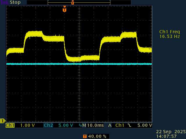
I pushed a little bit further my invesgations :
when I set the motor.target value much higher , the sin wave starts to became “square”
it is probably because of the µC load is far too high according its possibilities.right?
Please take a look at: Field Oriented Control | Arduino-FOC
It explains the relationship between motor voltage limit, driver voltage limit and power supply voltage.
Regarding the monitoring, printing too much from the main loop causes problems, this is known. That’s why the downsample for the monitoring is set to 100 by default, and you can increase it further as needed.
It’s also true as Deku said that printing to serial has different performance impacts depending on the MCU type and framework used. STM32F1 isn’t the fastest MCU type, and doesn’t have a FPU so your performance will be limited a bit by that. Still, normally we would not expect the monitoring (with downsample of 100 or more) to have such a big impact, so I wonder if there is something additional going on. What kind of position sensor are you using? Is the clock configuration for the board correct, so that the MCU is running at a fast clock speed?
And what’s the serial setup? What speed is it configured to, or is it using USB serial?
hi
actually, system is configured as velocity_openloop and torque control voltage, as required before.
monitoring is no more used (but when it was downsampling ration was set to 1:1000)
What kind of position sensor are you using?
nothing change on the board since the very begining of my course : hall sensor, legacy , into the wheel (Onewheel hardware , known in good condition)
Is the clock configuration for the board correct, so that the MCU is running at a fast clock speed
no idea sir! ![]() I’m also surprised that the code does something “out of the box” … almost magic, I know that clock structure isn’t a small part , … and I don’t have a clue to where it is set …
I’m also surprised that the code does something “out of the box” … almost magic, I know that clock structure isn’t a small part , … and I don’t have a clue to where it is set …
And what’s the serial setup? What speed is it configured to, or is it using USB serial?
monitoring is no more used in main loop, but it is set to 115.2Kbds
thanks for your interest
F_CPU return 64Mhz ![]() , the last time I used a µC, clock with 4Mhz full throttle … a small Tiny85 from atmel…
, the last time I used a µC, clock with 4Mhz full throttle … a small Tiny85 from atmel…
so , it is now a kind of mystery….
void loop()
{

 // digitalWrite(leds[0], HIGH);
//________normal section
  // main FOC algorithm function
  digitalWrite(leds[0], LOW);
   digitalWrite(leds[0], HIGH);
  motor.loopFOC(); //2µs

  // Motion control function
  motor.move(); //3µs

   // display the currents
 // motor.monitor(); //<= sinewavekiller! can take 2ms to complete!
//________end normal section

}
allow me to report some measurment , I used my scope and an output to catch execution time :
motor.loopFOC(); //2µs
and
motor.move(); //3µs
I also measure motor.monitor , and it takes sometimes 2ms .
so it reasonnable to say that µC isn’t so much loaded.
if I push from motor.target=5 to motor.target=15 , sinus wave loose its shape, and timings remain the same….
mystery again…..
It’s still not clear what’s happening…
but 2us + 3us is only 5us or 200kHz - that’s much faster than your PWM speed. You should slow that down a bit…
what do you mean?
it is clear for me that my loop should be as fast as possible. The evidence here is that µc burden is very light.
cannot explain such a wave shape degradation…..