True Torque controller

Hi everyone,

I was thinking about the library modifications which will be necessary in order to provide a true torque controller mode to the SimpleFOC library.

The torque controller mode already included in SimpleFOC is a basic one because it can’t take care of the back EFM generated when the motor is spinning. In some application this is a huge drawback because the torque can’t be controlled precisely over the full speed range.

I propose to detail here some research i did concerning torque control of PMSM. Feel free to comment, correct my words and help us to make a better piece of software, help will be appreciated :slight_smile:

So before trying to improve the library let’s have a look at what we already have! The diagram below is a representation of the torque controller available in the current version of simpleFOC :

Concerning the color scheme:

  • Red box are hardware parts

  • Yellow box are code which have to be specific for each MCU or MCU Family

  • Blue box are small piece of software functionality which can be common to all target

  • White box are SimpleFOC function name supporting the blue box functionality.

In my opinion we shall discuss only about the white and the blue box here. Because as we saw with the Advice On Current Sensing thread, sometime, practical implementation can be a huge topic by itself. That’s why I propose to just imagine here that’s we are able to get current, position and speed in a perfect manner on each MCU which will run SimpleFOC, and discus only what can we do with this values.

What i propose to implement is an improved torque controller based on the current flowing through the motor coil, the user can choose according to is board capabilities if it will use the already implemented voltage controller or the new one based on current measurement:

// Motion control type
enum ControlType{
 torque,// Torque control
 velocity,// Velocity motion control
 angle// Position/angle motion control
};
// Current
enum TorqueControlMode{
 voltage,// Torque control using voltage (Openloop)
 current,// Torque control using current (Closedloop)
};

Below is the diagram of considered the solution :

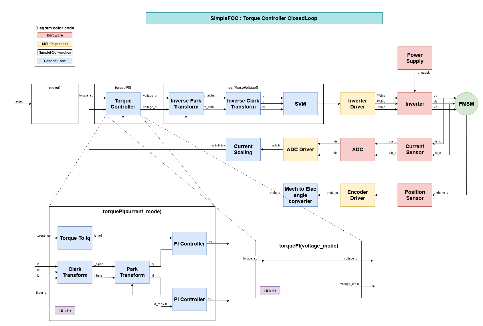
In case of TorqueControlMode set to voltage then the already implemented controller will be used. The input of the control is a voltage provided by the user or by a higher level loop.

In case of TorqueControlMode set to current. The input of the torquePI function will be a torque in N.m provided by the user or a higher level loop like a speed controller.

In the two configurations the torque setpoint can be set by the move() function as usual.

This approach will require a little rework of the setPhaseVoltage() function because the setphase voltage assume a voltage_d equal to 0.

We can now focus on the implementation of the torquePI() function in current mode :

This torque_sp variable will be used as an input for a new torquePI() function. This function will need all current flowing through the motor, the electrical angle and the torque setpoint in order to compute voltage_q and voltage_d required by the modified setPhaseVoltage function.

Hereafter the detail for each torquePI block:

Clark & Park all in one function

float C2d3 = 0.66666666666666666666666666666667;

float C1d3 = 0.33333333333333333333333333333333;

float C1dsqrt3 = 0.57735026918962576450914878050196;

float a,b,cosine,sine;

a = C2d3*(*ia) - C1d3*((*ib)+(*ic));

b = C1dsqrt3*((*ib)-(*ic));

cosine = cos((*theta_e));

sine = sin((*theta_e));

*d = a*cosine + b*sine;

*q = b*cosine - a*sine;

PI Controller

PI Controller already implemented in the library can be used here.

Torque To Iq

The Electric Torque of a PMSM is depending of this architecture, for a surface mounted magnet the torque equation is as simple as:

Te = (3/2)npmagnet_flux*iq

And magnet flux is equal to: (2kt/(3np)) with Kt the motor constant torque and np the pole pair number of the motor.

So

Te = Kt * iq

For an internal mounted magnet motor this equation is not valid, but for all gimbal brushell motor it dosen’t matter because they use always surface mounted magnets.

That’s it for the moment, don’t hesitate to give your opinion about this approche :slight_smile:

Best regards,

1 Like

Hello Robin,
There are good ideas, but I have got a question about the first approach current and the simplest.
We can get the current from this way (?) and the back emf with :
I (in A) = (motor.voltage_q - (KE *_SQRT2) *sensor.getVelocity())/Z
and we can deduce the torque :
T (in Nm) = KT*I
with

  1. KE is the Back EMF constant in general in Vrms/K RPM from the factor “_SQRT2”
  2. motor.voltage_q is the voltage applies to the phase
  3. sensor.getVelocity() is the current velocity
  4. Z is the impedance with
    Z=_sqrt(L*L*sensor.getVelocity()*sensor.getVelocity() + R*R)
    we can remove the effect of the coil, if (R >> L) => Z = R (if the curve of velocity in function of the torque is almost a straight line).
  5. KT is the torque constant in Nm/A
  6. Back emf is the result of KE*_SQRT2*motor.getVelocity()

Of course, we can’t directly get the current as would be for the second approach, but it is a way to get it, and it would be interesting to add it in the first approach too.

Best regards.

There were display problems:

I = (motor.voltage_q - (KE x SQRT2) x sensor.getVelocity()) / Z

T = KT x I

Z = SQRT( (L x L) x sensor.getVelocity() x sensor.getVelocity() + (R x R) )

Hey @robin2906 and @Marc_O

Thanks for the great proposals!

Ok, so few days ago I’ve received the SimpleFOCShields with in-line current sensing and I was able to create a very similar approach to what @robin2906 has explained in detail in his post. This is the real FOC solution for torque control and the library will definitely go in that direction for the future steps.
But since the current sensing is a big constraint we will try to implement more than just this approach.

@Marc_O I think your approach is a great idea to upgrade our voltage control loop. I was actually thinking about this. To add the estimation of the backemf and estimate the current, I think this could be pretty cool and simple to implement and I will definitely look into it!

@robin2906 Thanks for the detailed explanation.
First of all, the library version v2.0 now supports setting d and q voltage separately. setPhaseVoltage has been updated ( only for SinePWM commutation though ).
I agree with basically everything you have said and I think it is the best way to proceed for the torque control.

I’ve actually implemented a version of it in an Arduino sketch ( completely outside the library ), here is the code:

/**
 * 
 * Torque control example using current control loop.
 * 
 * This example is based on stm32 Nucleo-64 board in combintaiton with the Arduino SimpleFOCShield V2.0
 * 
 * The current is measured inline with the shunt resistor or R= 0.01 Ohm, and amplification gain og G=50 
 */
#include <SimpleFOC.h>

// BLDC motor & driver instance
BLDCMotor motor = BLDCMotor(11);
BLDCDriver3PWM driver = BLDCDriver3PWM(5, 10, 6, 7);

// encoder instance
Encoder encoder = Encoder(2, 3, 500);

// Interrupt routine intialisation
// channel A and B callbacks
void doA(){encoder.handleA();}
void doB(){encoder.handleB();}

void setup() { 
  
  // initialize encoder sensor hardware
  encoder.init();
  encoder.enableInterrupts(doA, doB); 
  // link the motor to the sensor
  motor.linkSensor(&encoder);

  // driver config
  // power supply voltage [V]
  driver.voltage_power_supply = 20;
  driver.init();
  // link driver
  motor.linkDriver(&driver);

  // set motion control loop to be used ( doing nothing )
  motor.controller = ControlType::voltage;

  // initialize motor
  motor.init();
  // align sensor and start FOC
  motor.initFOC();

  // use monitoring with serial 
  Serial.begin(115200);
  Serial.println("Motor ready.");
  Serial.println("Set the target current in milli Ampers:");
  _delay(1000);
}

// target voltage to be set to the motor
float target_current = 2;

// currents
float ia, ib;
float ialpha, ibeta;
float id, iq;

// PID controllers and low pass filters
PIDController PIDq{10,1000,0,100000,20};
PIDController PIDd{10,1000,0,100000,20};
LowPassFilter LPFq{0.0005};
LowPassFilter LPFd{0.0005};


// counting variable for user display
long t = 0;
void loop() {
  ia = (analogRead(A0) - 512.0)*0.00644;//*3.3/1024.0/50.0/0.01; // amps
  ib = (analogRead(A2) - 512.0)*0.00644;//*3.3/1024.0/50/0.01; // amps

  // clarke
  ialpha = ia;
  ibeta = _1_SQRT3*ia + _2_SQRT3*ib;
  
  //float theta = motor.shaft_angle*motor.pole_pairs;
  float theta = _normalizeAngle(_electricalAngle(motor.shaft_angle, motor.pole_pairs));
  float ct = _cos(theta);
  float st = _sin(theta);
  // park
  id = LPFd(ialpha*ct + ibeta*st);
  iq = LPFq(ibeta*ct - ialpha*st);
  
  motor.voltage_q = PIDq(target_current/1000.0 - iq);
  motor.voltage_d = PIDd(-id);
  

  // set the phase voltages Ud and Uq
  motor.loopFOC();


  // show user the currents
  if(!t){
    Serial.print(id*1000); // mAmps
    Serial.print("\t");
    Serial.println(iq*1000); // mAmps
  }
  t > 1000 ? t = 0 : t++; 

  // communicate with the user
  serialReceiveUserCommand();
}


// utility function enabling serial communication with the user to set the target values
// this function can be implemented in serialEvent function as well
void serialReceiveUserCommand() {
  
  // a string to hold incoming data
  static String received_chars;
  
  while (Serial.available()) {
    // get the new byte:
    char inChar = (char)Serial.read();
    // add it to the string buffer:
    received_chars += inChar;
    // end of user input
    if (inChar == '\n') {
      
      // change the motor target
      target_voltage = received_chars.toFloat();
      Serial.print("Target current [mAmps]: ");
      Serial.println(target_current);
      
      // reset the command buffer 
      received_chars = "";
    }
  }
}

As you can see the schema is basically the same as you have shown, the only difference is that I’ve added the a pair of low pass filters for each current component.

I’ve tested this code on stm32 nucleo f401re and Arduino UNO so far and the results are very different.
Nucleo board loop() execution time is around 10kHz and Arduino UNO is more around 1kHz. And at the moment this seems to be the limiting factor.

At the moment, I am not sure that the benefits of this type of control will be visible for Arduino UNO really. Due to the low processing power Arduino UNO is not able to run these motors with high velocities and for low velocities even the voltage (open) loop shows good results. But overall, I am happy to see that this actually works and am looking forward to include “true” torque control in the next release of the SimpleFOClibrary but also the SimpleFOCShield.

1 Like

Hello @Antun_Skuric, @robin2906,

@Antun_Skuric Your last version 2.0 is great, it really is an improvement and more structured, well done. Otherwise, I had just a little bit precision about the formula of the current as I have shown above, as KE is in Vrms/Krpm (standard) and sensor.getVelocity() in rd/s, I propose you to put a constant factor equal to :

#define KE (x.xx) // Back emf in Vrms/KRPM
#define BEMFC ((_SQRT2 * _2PI / (1000 * 60)) * KE) // BEMFC is the Back emf in Vpeak/rd/s

and the formula becomes:

estimate.current = ( motor.voltage_q - BEMFC * sensor.getVelocity() ) / Z

Another stuff, the _sqrt from the formula of Z can be a classic fast sqrt implemented in the foc_utils.cpp:

Blockquote
// Fast sqrt
float _sqrt(float n) {
n = 1.0f / n;
long i;
float x, y;
x = n * 0.5f;
y = n;
i = *(long *)&y;
i = 0x5f3759df - (i >> 1);
y = *(float *)&i;
y = y * (1.5f - (x * y * y));
return y;
}

Therefore from formula here above, the limit torque could be controlled by :
motor.voltage_limit = target_current * Z + BEMFC * motor.target_velocity;
with target_current in Amps, motor.target_velocity in rd/s, motor.voltage_limit in Volt.

@Antun_Skuric, @robin2906 In the second approach, we can deduce an estimate velocity from the current reading with:

estimate.speed = (motor.voltage_q - Z * motor.current) / BEMFC

with

  1. motor.voltage_q is the voltage applies to the phase
  2. Z is the impedance in ohms
  3. motor.current the current reading in Amps
  4. BEMFC the backemf constant in Vpeak/rd/s
  5. estimate.speed is in rd/s

Therefore, you could implement estimate functions in the both approach in the future, as shown above…

Your thoughts ?

Hello@ robin2906 @system_admin_ Skuric

This is a great topic! Learned a lot! I imitate David_ Gonzalez board is driven by drv8305. I can see that IA and IB 2 phase currents are used in your code. In the process of looking at the algorithm, Ia + IB + ic = 0, is the current of IC phase not in the algorithm? Calculation I_ alfa,i_ Beta does not require IC?

The formula is as follows:

Iα = Ia ;

Iβ = (Ia + 2*Ib) / √3 ;

If Ia + IB + ic = 0, is it possible

Iα = Ia ;

Iβ = Ib/ √3- ic/ √3;

I use the drv8305 driver to sample the IA, IB and IC three-phase current. In other words, the second formula can be used to calculate the three-phase current directly? Another question is, how much difference will be made between the two methods?

Hey guys,
I’ve spent some time on this topic recently and using the new SimpleFOCShield v2.0 board I was able to god pretty good results.

Here is a video of the velocity control loop with current sensing + limiting:

The code that I used is the basically the same as the code from before. Here is the arduino

/**

   Torque control example using current control loop.

   This example is based on stm32 Nucleo-64 board in combintaiton with the Arduino SimpleFOCShield V2.0

   The current is measured inline with the shunt resistor or R= 0.01 Ohm, and amplification gain og G=50
*/
#include <SimpleFOC.h>

// BLDC motor & driver instance
BLDCMotor motor = BLDCMotor(11);
BLDCDriver3PWM driver = BLDCDriver3PWM(5, 10, 6, 8);

// encoder instance
Encoder encoder = Encoder(2, 3, 500);

// Interrupt routine intialisation
// channel A and B callbacks
void doA() {
  encoder.handleA();
}
void doB() {
  encoder.handleB();
}

//MagneticSensorI2C encoder = MagneticSensorI2C(AS5600_I2C);

// center remove for bidirectional current sensing
float center_ia=0;
float center_ib=0;
void setup() {

  // initialize encoder sensor hardware
  encoder.init();
  encoder.enableInterrupts(doA, doB);
  // link the motor to the sensor
  motor.linkSensor(&encoder);

  // driver config
  // power supply voltage [V]
  driver.voltage_power_supply = 12;
  driver.init();
  // link driver
  motor.linkDriver(&driver);

  // set motion control loop to be used ( doing nothing )
  motor.controller = ControlType::voltage;

  // initialize motor
  motor.init();
  // align sensor and start FOC
  motor.initFOC();

  // use monitoring with serial
  Serial.begin(250000);
  
  _delay(1000);
  //  Serial.println("Align currents.");
  for (int i = 0; i < 500; i++) {
    center_ia += analogRead(A0);
    center_ib += analogRead(A2);
  }
  center_ia = center_ia / 500.0;
  center_ib = center_ib / 500.0;
  _delay(1000);
}

// target velocity
float target_velocity= 0;

// currents
float ia, ib,ic;
float ialpha, ibeta;
float id, iq;

// PID controllers and low pass filters
PIDController PIDv{0.2, 30, 0.005, 10000, 3};
LowPassFilter LPFv{0.001};
PIDController PIDq{5,1000,0,100000,12};
PIDController PIDd{5,1000,0,100000,12};
LowPassFilter LPFq{0.001};
LowPassFilter LPFd{0.001};


// counting variable for user display
long t = 0;
float target_iq = 0;

void loop() {
  // nucleo
   ia = (analogRead(A0) - center_ia)*0.00644;//*3.3/1024.0/50.0/0.01; // amps
   ib = -(analogRead(A2) - center_ib)*0.00644;//*3.3/1024.0/50/0.01; // amps

  // clarke
  ialpha = ia;
  ibeta = _1_SQRT3 * ia + _2_SQRT3 * ib;

  float theta = _normalizeAngle(_electricalAngle(motor.shaft_angle, motor.pole_pairs));
  float ct = _cos(theta);
  float st = _sin(theta);
  // park
  id = LPFd(ialpha * ct + ibeta * st);
  iq = LPFq(ibeta * ct - ialpha * st);

  motor.voltage_q = PIDq(target_iq - iq);   
  motor.voltage_d = PIDd(-id);


  // set the phase voltages Ud and Uq
  motor.loopFOC();


  // show user the currents
  if (!t) {
    target_iq = PIDv(target_velocity- LPFv(encoder.getVelocity())) / 10.0;
    Serial.print(iq * 1000); // mAmps
    Serial.print("\t");
    Serial.println(id * 1000); // mAmps
  }
  t > 10 ? t = 0 : t++;

  // communicate with the user
  tuneController();
}


// Serial communication callback function
// gets the target value from the user
void tuneController() {
  // a string to hold incoming data
  static String inputString; 
  while (Serial.available()) {
     // get the new byte:
    char inChar = (char)Serial.read();
    // add it to the inputString:
    inputString += inChar;
    // if the incoming character is a newline
    // end of input
    if (inChar == '\n') {
      if(inputString.charAt(0) == 'A'){
        PIDq.P = inputString.substring(1).toFloat();
      }else if(inputString.charAt(0) == 'B'){
        PIDq.I= inputString.substring(1).toFloat();
      }else if(inputString.charAt(0) == 'C'){
        PIDd.P= inputString.substring(1).toFloat();
      }else if(inputString.charAt(0) == 'D'){
        PIDd.I = inputString.substring(1).toFloat();
      }else if(inputString.charAt(0) == 'E'){
        LPFq.Tf=inputString.substring(1).toFloat(); 
      }else if(inputString.charAt(0) == 'F'){
        LPFd.Tf =inputString.substring(1).toFloat(); 
      }else if(inputString.charAt(0) == 'G'){
        PIDv.P = inputString.substring(1).toFloat();
      }else if(inputString.charAt(0) == 'H'){
        PIDv.I = inputString.substring(1).toFloat();
      }else if(inputString.charAt(0) == 'I'){
        PIDv.D = inputString.substring(1).toFloat();
      }else if(inputString.charAt(0) == 'J'){
        LPFv.Tf = inputString.substring(1).toFloat();
      }else if(inputString.charAt(0) == 'k'){
        PIDv.limit= inputString.substring(1).toFloat()/100.0;
      }else{
        target_velocity=inputString.toFloat();
      }
      inputString = "";
    }
  }
}
1 Like

Can anyone recommend a suitable/compatible high torque motor in the 100-300Nm range?

ATO has one for 110Nm peak torque, you would need a custom driver though. Also, you may approach Siemens or Toshiba. These motors usually cost $10,000 and above. My electric car has a 200 Nm motor by Bosch. You may call them and ask.

Another option would be to look for geared servos such as those, however, they are rather slow.

http://www.phaseusa.us/ultract-3-servo.html

PS Another, questionable option IMO, would be to buy a used golf cart and pull the motor out if you need a cheap one for testing. This needs a lot of space and a full garage / workshop.

Please don’t hurt yourself.

Cheers,
Valentine

1 Like