Advice on Current Sensing for new board design

I’m in the process of designing my first custom PCB and (of course) will be running simplefoc on it!

Features stm32f405 (170MHz), 3x l6234d, 3x i2c buses, 1xSPI (with 3 chip select pins), can, usart, st-link, 9 auxillary pins. It’s heavily inspired by Phil’s lab kikad tutorial.

I’ve done the basic design in kicad whilst using stm32cube config tool to work out compatible pins but am uncertain on how to get current sensing scaled sensibly to be read by stm32 ADCs. You’ll notice in the diagram that I’m using L6234d (same as simplefoc shield). This driver has support for torque/current measurement through 1 shunt resistor (i.e. not per phase current measurement). I want to get this value back into SimpleFOC to act in a similar way to voltage_limit. Controlling voltage_limit is roughly equivalent to controlling torque, but using shunt resistor measurements should be closer to true torque control.

What I’ve currently got (see schematic) will measure the voltage across shunt directly using an ADC pin on stm32. I don’t (yet) have an opamp (or similar) to boost voltage and am unsure of the calculations. Assuming I want to connect a range of motors from 1 ohm to 15ohms per phase winding - what would you suggest for shunt resistors and voltage boosting? It’ll be a jlcpcb assembly job so I’m limited to their basic/extended parts (I don’t want to solder this bad boy!).

Other critique/comments on design appreciated.

2 Likes

While I am not 100% sure on how to help you with the resistor, I think this application note might help. Specifically page 7 of it.


Also, I would like to point out something about your CAN interface.

At the moment, you can the CANRX and the CANTX of the microcontroller directly connected to a connector. Wouldnt it be easier to have a CAN transceiver aboard of your board?

If you don’t know what a CAN transceiver is, it is basically a small IC that converts the two signals coming from your microcontroller (CANRx & CANTX) into two signals understood by other CAN nodes (CAN HIGH & CAN LOW).

Also, I would recommend adding a 120 ohm termination resistor for your CAN bus. You could potentially have this one connected to a switch/jumper so you can turn it on or off.


Then, in general it can be very useful to expose extra 3V3, 5V and GND to connectors. These can be useful when using the auxillary outputs you have planned for.

A tip I learned after debugging countless of boards is adding testpoints to a lot of places that can be troublesome. Testpoints make it easier to connect your oscilloscope to troublesome areas. I usually have test points for both USB signals (be careful here not to mess with the impedance too much) and crystal traces. In this case, test points for the PWM and enable signals to the L6234 might save you a ton of headaches as well.


EDIT: Is it me or are you missing a reset button? I can’t see where the other end of NRST is connected. I also think you will need some kind of jumper or button to toggle the state of the BOOT0 pin, correct me if I’m wrong.

Altough both of these pins aren’t necessary to be switched if you’re using an ST-LINK as a programmer, but then they could still be nice to have. Especially a reset button.

Thanks for your advice @Luca, you’ve clearly had a good look at the diagram. Your time is appreciated.
Yes the l6234 datasheet sort of talks about current sense but it’s not clear. Page 12 shows more details but is complex and is combing torque with speed control using hall effects - which isn’t the pattern I’m looking for.
The can transceiver is something I’ll look into - its a shame that its an extended part on jlpcb - I was hoping to keep the price under £30, how much do I want that can bus :thinking:. The 220ohm resistor goes the other side of the transceiver, right? I’m also considering adding a mpu-6050.

The other end of NRST is connected to ST-Link. I know what you mean about reset button. Phil (link above) didn’t have reset/boot buttons for his board, he justified it by saying that he only resets when programming, but as you mentioned it is nice to have.
I don’t have a USB. What is weird with these stm32s is that you typically don’t get printf through USB and because st-link gives you full debug/breakpoints it really helps to program using st-link.

No problem, always here to help :slight_smile:

You can leave the transceiver off and solder it on yourself, there are some that are very easy to hand solder. Like this one. (This one even offers galvanic isolation if you would want that) The 120 ohm resistor goes between CAN HIGH and CAN LOW, the output of the transceiver.

Leaving out the reset button is an understandable choice, especially because most of them (if not all) are extended JLC parts as far as I know.

If you are planning on programming this board with Arduino, you won’t have debug/breakpoints over the st-link. Last time I worked with the stm32duino this didnt exist. Also don’t expect to be using platformio because their support of stm32duino is horribly old.


Actually quite funny you’re working on a project like this, I sent Antun a personal message earlier today asking if he wanted to collaborate with me on a similar board that can be sold next to the SimpleFOC shield. I would go for the same STM as on the bluepill as that one is the best supported by stm32duino and very very easily available.

Let me know if you have more questions, I am happy to help. Looking forward to seeing your board layout! :smiley:

1 Like

I only use platformio and yes I’ve bumped into a few stm32duino issues but st-link debugger generally works. The stm32f107 (blue pill) is a basic part, I could swap current Arm M4 chip but I’d lose a fair bit dropping to Arm M3 (e.g. half speed, less timers, etc). Decisions! I also noticed that the esp32-pico-d4 is another option (extended part), but I suspect you can’t do a triple driver. Also the ADC on esp32 is notoriously bad. I’m tempted to ignore those failings, for that second core!

PM me if you want to collaborate. I’d been interested to know how close your ideas are to mine.

Hi Owen

Like mentioned in another thread the MAX40056 is awesome in pwm applications. It does have a quite large footprint at the moment, but will soon be available in a really small package (next year). Do not know if your assembly house has got that IC.

Remember the appropriate trace width and clearance if you are going for thicker copper.

2 Likes

Hi Owen,

Impressive project ! Maybe I can give you some advices :wink:

The L6234 can drive current up to 5A right? So first I think you can’t use a 0.25 ohm as a shunt resistor because at full load the power dissipated by the resistor will be equal to 3RI^2 = 30.255*5 => 18.75 W!! (The 3 is because on your schematic you connected all the three branch of the driver on the same shunt resistor). A resistor which dissipate 18W is not called a resistor anymore but a heater :wink:

Secondly, it will be difficult to use the resistor on your schematic as a current sensor because the resistor will act as a sensor only when the low side of the L6234 is commuted so you will need to synchronize your PWM with the ADC acquisition. Something that is difficult to archive with the simple foc library. Moreover, as you can sample the current only when the low side of the L6234 is on it will be difficult to sense the current for low PWM ratio because the sampling time of the ADC will be more than the PWM low state duration.

Of course, you cannot decrease the shunt value to 25mOhm… the maximum power dissipated by the resistor will be 1.875 W but the dropout voltage sampled by the ADC will be 0V for 0A and 0.0025*5 = 0.0125V for 5A in the coil. As the STM32 ADC is a 12 bits with à full range of 0 to 3.3V the quantum of the ADC is equal to 3.3/ 2^12 => about 0.0008V. Therefore, in your application with a shunt of 25mOhm your current sensing resolution will be 0.0125/0.0008 => 15 LSB. 5A/15 = 0.333 mA … which is not really optimized :wink:

The solution proposed by Juan-Antonio_Soren_E seems more reasonable; it cost more in terms of BOM price and PCB space but will work like a charm. You will need only 2 MAX40056 by L6234 and 2 shunt resistor. The MAX40056 is not in the JLCPCB library but the AD8206 is equivalent and can be provided by JLCPCB in the extended library. Moreover, with inline current sensing you can sense the current when you want in your PWM cycle, you do not need to synchronize current sampling with PWM so it will keep your code close to the simpleFOC original library! You only need 2 sensor by motor because you can use i1+i2+i3 = 0 in a brushless motor so if you sample I1 and I2 then you can compute I3 = -I1-I2.

Have a good day :slight_smile:

3 Likes

Hi Owen,

impressive work.
What about switching to the stm32g4 series? They come with integrated OpAmps. A 0,015 Ohms resistor would lead to a thermal los of 0,375 W, which is acceptable in my opinion. The OpAmps have programmable gains from 1 to 64. So a 0,015 Ohm Risistor would cause a voltage drop of 0,015 * 5A * 64 = 4,8 V. I rather consider to use the stm32g4 series instead of the f series along with the MAX ICs due to pcb space in my project.

And one more thing. In my opinion the 220nF Capacitor of the Bootstrap should be connected to Vs instead of ground. The datasheet of the 6234 as well as the datasheet of the 6230 depicts it this way. Only the diagramm here https://www.st.com/en/motor-drivers/l6234.html got it the other way.

Hi Mr. Anderson,

Good point for the STM32G4.

In my opinion, the main drawback of the STM32G4 is that it can only be used as a low side current sensing because the input common mode voltage tolerate by each OPAMP in the MCU is VDDA max.

The low side current sensing topology induce a lot of work in terms of software. You will need to synchronize ADC and PWM.

Nevertheless, if you can handle this it could be a good option :slight_smile:

Best regards

Hi robin,

can you explain the PWM and ADC synchronization in detail or give me an external link where i can read about it? I am not aware that this could be an issue.
From my understanding i have to measure the current in at least two phases and use the clark transformation in order to calculate the corresponding vectors and set the PWM signal for the 3 half bridges.

Do you mean that the problem is that the low side current of each h-bridge is not equal to the phase current? Why is that?

Some great points given. Jlcpcb has some sense resistors. Will take a look at those. I’ve got a stm32g4 disco, didn’t realise it has opamps. Interesting. A bit of a concern is how easy these would be to configure from stm32duino core. I’ll look at Vc capacitor.

I’m wondering whether i should be looking at a smarter driver. I’ve been meaning to ask @David_Gonzalez about how he is doing current sensing on his dagor controller. This may mean dropping l6234 for a drv83xx chip and adding mosfets. Another area I know little about!

Nevermind, i got the problem. this helped a lot:

My suggestion can even be deadly for the build in ADCs of the STM32g4, since the voltage drop during the on state of the low side mosfet is negative due to the free-wheeling current.

No problems, it is easy to understand :slight_smile:
You can see below a schematic of a low side current sensing architecture.

In a low side current sensing topology the current flow through the shunt resistor only when the low side transistor of the branch is switched on. If your ADC sample the shunt voltage when T3* is not conductive then no current flow through the shunt resistor and you will not get the current flowing through the coil.

Another problem: If your ADC have a minimum sample time of 25us (for example) how do you sample the current when T3* is switched on for 25us or less? The answer is simple: you can’t…

From my understanding I have to measure the current in at least two phases and use the Clark transformation in order to calculate the corresponding vectors and set the PWM signal for the 3 half bridges.
You are right, in a middle performance brushless driver you can assume that i1+I2+i3 = 0 so if you sample only 2 current then you can easily compute i3 without actually measuring it.

In some design, you will find one shunt resistor on each phase of the driver. That’s can be useful when a branch have a low side commutation time lower than your ADC sample time… You can use the measurement of the two other phase (with a long low side commutation time) for computing the current is this unmeasurable branch.

Selecting which branch have the longest low side commutation time have to be done in software which bring complexity to it …

This is Nice, i love good arguments.

Considering the dev. on steppers. If you are going for inline sensing and 4 bridges, you can measure the current flow in both directions. The MAX ic is bidirectional.

Hi Owen,

DRV82xx use low side or high side current sensing. Each will need synchronization between PWM and ADC…

In my opinion, the simplest architecture for easy integration with simple FOC is in-line current sensing:

This topology need dedicated amplifiers with wide input common mode voltage but the current can be sampled without PWM synchronization and only two branch have to be sampled so it will keep the simple FOC library efficient.

@Owen_Williams I have lost many nights over this, and I’m still not sure how I will approach current sensing with my current hardware.

@robin2906 explained it perfectly. With the DRV8305 I’m doing low-side current sensing and this is straight from the ADC:

If I can’t figure out a way to sync the measurements with the PWM signal I’ll probably use a low-pass filter and use current sensing to apply/find a voltage limit in terms of current, and to detect collisions.

If somebody has any suggestions on how to do this with the ESP32 please let me know over: ESP32 Brushless controller - Dagor (work in progress)

@David_Gonzalez I’m happy for this thread to drift into general strategies/ideas on current sensing.

Can you explain the graphs a bit (I’m being a bit slow!). Is your drv8305 actually measuring the current, amplifying, and putting the results on an an analog pin for mcu to measure via adc?

I don’t understand why the sinusoidal waves have those cuts in them. Are they 50% duty? Are you only suppose to measure each phase when low or high gate is in use? I’d understand the graphs if they were pwm only (not sinusoidal) as I’d expect real current to be pwm.

I take it you want current readings for reading torque and not for sensorless position. Perhaps taking a moving average is good enough (or even correct!)

What we’re seeing on the graph is the voltage drop across the sense resistor after a 10x amplification on the DRV8305 measured directly from the ESP32’s ADC. If my understanding is correct the fact that we’re seeing sinusoidal signals is that current doesn’t behave like voltage and even if you have a PWM (pulsating voltage) signal you don’t necessarily see pulsating current.

The reason that we are seeing the cuts in the waves is the fact that the sense resistors are located after the low side FET so when the FET is off the voltage across the sense resistor will ultimately be 0. This wouldn’t be an issue if you do in-line current sensing as @robin2906 suggested.

You’re correct :slight_smile: I want current sensing to do torque control and to detect collisions in direct or quasi-direct drive systems.

Awesome project! I’m working on a similar design, and happy to exchange information if you want.

For the current sensing: as some people have already mentioned, you need to size the shunt resistor so that:
a) your max power dissipation (given by the voltage drop on the shunt x the max current, probably 5A for a 6234 driver) must be well within the power rating for the shunt, or it will burn up
b) your voltage drop is as large as possible (makes readings more accurate and less noisy)
So you basically pick the largest value that (with some safety margin) doesn’t burn

Since you’re using a single shunt sensing topology, you probably don’t want to use the current sensing to drive the FOC algorithm in terms of motor position, so you will still need an accurate encoder. But you can use the current sensing to drive motors with lower winding resistances by implementing current limiting. Note that this is currently not implemented in the SimpleFOC library, I think.

For a 1 Ohm winding resistance, I think your shunt value will need to be quite low, and you will definitely need to amplify the voltage. For this an op amp is what you need, but I would strongly recommend using a current sense amp (a ready made IC integrating most of the stuff you need as well as filtering circuitry etc). This is where it starts to get quite complicated, because you will need to choose the op-amp or current sense amp according to the needs of the application. So in your case you need a common mode that can go (at least a little bit) negative, 16(?)V input, fast response times, and can map the positive/negative voltages you get from the shunt to a positive only voltage the microcontroller can work with. You may also need to use some kind of voltage reference to provide a stable reference voltage to the amp. Take a look at the INA*** current sense amps, they have some useful models.

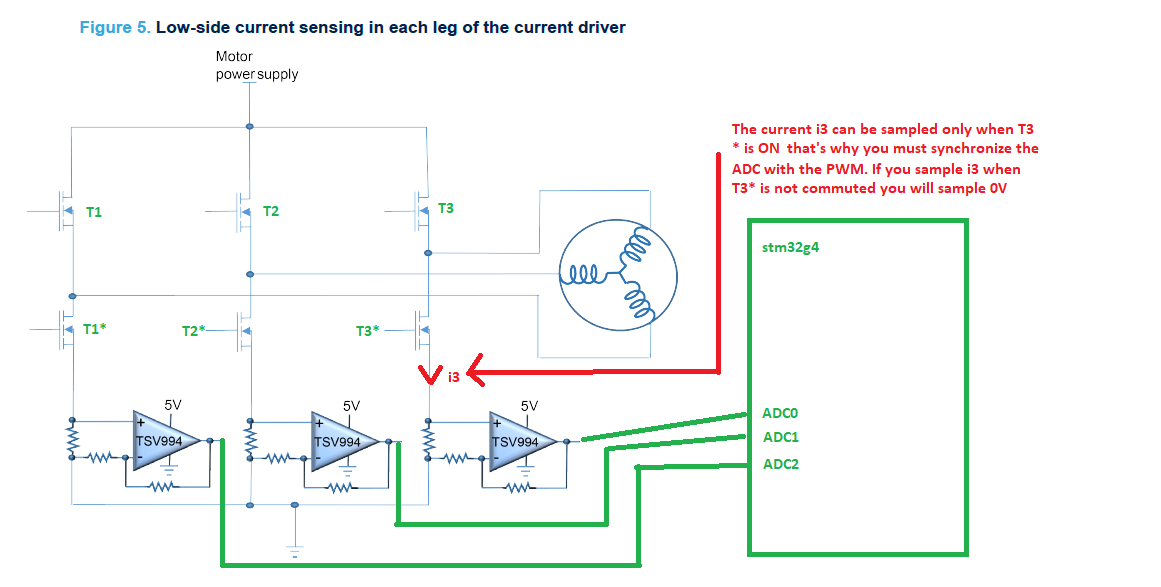
From there it needs to go to the microcontroller. I’d be interested what your plan is for this. The STM32 have good ADCs, I think, and I think there are features to connect them to the PWM driving. Some models also have built in op-amps and comparators. I think the problem here is that the switch-off has to happen fairly quickly, probably faster than would happen if you just “read ADC, re-adjust PWM” in the FOC control loop. Many designs I’ve looked at use comparators to detect the over-current condition and switch the EN or IN control signals low using hardware, and not software. Some of the motor driver chips also have dedicated inputs for this purpose, so you can get a current control loop many times faster than your FOC control loop, maybe even considerably faster than your PWM period…

One final note: I’d urgently recommend doing some kind of simpler design as your first assembled PCB. Doing a motor controller with current sensing and microcontroller as your first project is very ambitious, IMHO. For example, why not start with just a part of it, as a breakout board, and use an existing microcontroller board to drive it?

Regards from Vienna,

Richard

Thanks Richard. Some great points! You are right about making my first board a bit simpler.

I’ve parked my custom board and want to see if I can add current sensing and 6PWM (i.e. 3 Drivers each with HIN and LIN) support to SimpleFOC - before returning to my custom board. I’m using the stm32g431 kit for drones to test the above (it comes with 3x shunt resistors).