Good afternoon, friends. Help solve the problem with using a stepper motor in a closed cycle. In an open loop, it works well. But in a closed cycle, its rotation is not uniformly clockwise. When it rotates counterclockwise, it makes half a turn and stops
Hey there! Hard to say, but there is definately a problem…
I assume the encoder is working well?
The fact that it acts differently in one direction to another makes me think there can be a problem with the electrical zero… either it is not being found right, or it is losing the absolute zero position, for example due to missed encoder pulses…
Hi @runger . I noticed that this happens with the command T5 and above. If the target value is below 4, then the rotor rotation speed floats as in the second video. In the third video, the target speed was 10.
5 or 10 rad/s is not that fast, so I would not expect problems.
When things are working in open loop, but not in closed loop, the problem is usually to do with the sensor, and sometimes with the parameters used, like the pole pair number.
Hello. I installed today another encoder, MT6701 in abz mode. But it still doesn’t work in a closed loop. I believe that the problem is the desynchronization of the phases of the motor and encoder. The engine does not rotate evenly. I want to plot the acceleration of the encoder at a constant rotor speed in an open loop, but I don’t know how yet. My knowledge of programming is not enough for this.
This is a transistor type driver, and it has the problem that it cannot support very short switching times. So in effect, there is a minimum PWM duty cycle it can deal with.
When using this driver, it can help to lower the PWM frequency, for example to 5kHz. This will give you a larger effective range of PWM duty cycles that you can use.
Before that, I used an encoder of 600 positions per revolution. There are 50 poles in a stepper motor, which means 12 steps of the encoder per one pole of the motor. But it seems to me that in fact this is not the case, sometimes more, and sometimes less. But I don’t know how I can check it and how it can be fixed programmatically…
Hmm, the MT6701 has a ABZ resolution of up to 1024 pulses per revolution, which equals 4096 CPR or 12bit accuracy. The datasheet doesn’t seem to say what the default setting is, you would have to use the I2C interface to check it…
1024PPR, this is better than 600PPR, but not a huge difference. At 50 poles it’s just over 20 steps per electrical revolution.
The encoder in ABZ mode, I assume you’re using the interrupt-based driver? Maybe the MCU is missing interrupt calls, this would explain if you get irregular step counts. You could try using this sensor in SSI mode - in this mode it has 14 bit accuracy, and is absolute, you can’t miss interrupts…
I reduced the frequency to 5kHz, but got only noise))))
As can be heard from the video, the rotor has a different angular velocity depending on the position of the rotor.
When rotating in the opposite direction, the rotor hangs in one position.
If, in order to rotate the rotor, the magnetic field of the stator must be 90 degrees ahead of the magnetic field of the rotor, then in my case this angle is not constant. And sometimes it has a lead of 0 degrees. That’s why the rotor stops.
If the controller were to skip interrupts, then I wouldn’t have a repeat state. As can be seen from the video, the rotor hangs always in one position, which indicates the absence of skipping interrupts
Hey, are you sure the problem is electrical/sensor related? From the look in the video it looks like there is a mechanical problem like some friction which happens during part of the revolution…
Is it possible to do a test? For example, to make 50 full steps of the motor and with each step to display the encoder readings? Theoretically, these readings should vary by one value. What if it’s not?
Sure, you can look in our examples directory, here:
You’ll have to adapt the code to your setup (stepper motor, etc) but you can use it as an example. It uses open loop mode to move the motor and prints the sensor values. It also calculates the error.
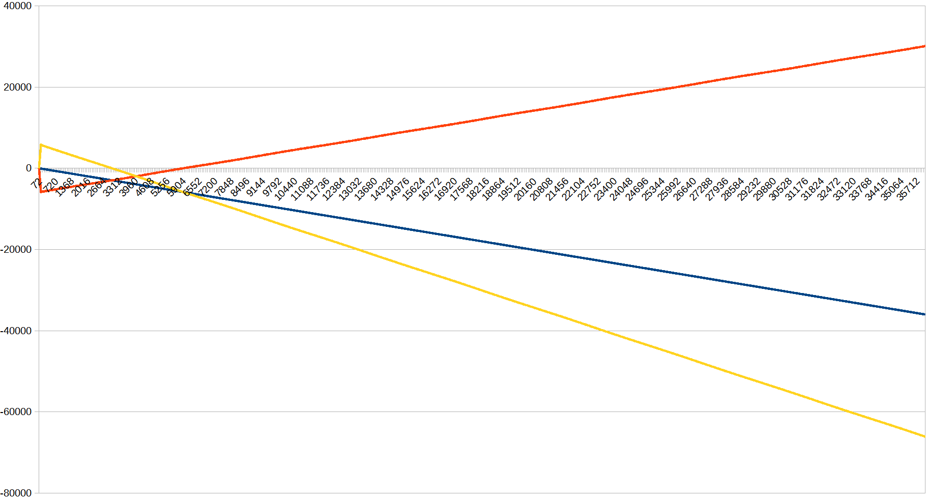
If you import these numbers into Excel or similar you can plot some nice graphs…
It looks to me like the sensor is not working at all
This explains why closed loop seems to work periodically – for the same reason a stopped clock is correct twice a day. Your sensor was “in the ball park” once per motor revolution.
I had this same issue with an AS5600 magnetc sensor. The firt thing to do is to readout and print the sensor while rotating the motor by hand. give it a half turn and do you see a half Pi difference on the screen, Does it go back to zero when you move it back? Basically you are using the sensor as a "volume control knob and the numbers should get bigger and smaller when you turn the knob. If this “hello world” sensor test fails, something is mis-wired.
I found LOTS of noise when I did this and found out that I needed to have the magnet not more then 0.5mm from the sensor chip, even if the specs said 3mm was OK.
For the above test just lay the magnet on the sensor and turn the magnet with non-magnetic plastic tweezers, or supper glue the magnet to the end of a wooden chopstick and spin the chopstick 1/4 turn at a time.
If the motor spins open loop then all the PWM, mosfets and power wire is correct. so net run the sensor but without the motor.
If both sensor and motor are OK, then the PID gains of grossly off. This is likey because the defaults are not for stepper motors
To tun a PID, start with all zero gains. The make P some very tiny number like 0.0001 and double it then try again untill the motor ocilates then go back then sneak up slowly untill it oscilates again then back off. Tunning is the “close enough”
A grossly wrong PID gain (order of magnitudes wrong) can make the motor jump around and run erratically
Hello. In the sensor test, when I manually rotate the motor rotor, it always returns to zero position in one turn. I’ll try otherwise, I have an A4988 driver for stepper motors. With it, I will take 200 steps and in parallel see what angle the sensor indicates.