Non-linear? Could it be the magnet is the wrong kind? They need to have the N and S poles across the face. Some magnets have N on one face and S on the other. It is easy to test if you have several magnets
Or maybe the magnet is grossly misalignmed and not concentric with the shaft. could it have come loose? I used super-glue
I have no experiance with a 50 pole motor but I’d assume the more poles the more accurate the sensor needs to be. I think you’d need to be sure the sensor is correct such that error is limited some fraction of a pole
When I had sensor noise the motor ran eratically or not at all but it was perfect in open loop.
One thing I did to debug is the AS5600 has a magnetic feild strength register that can be read out. I found it is very low.
Where are you located, both @runger and I have the MT6835 stocked, I suspect you can get past these bugs by switching to that sensor. I totally get if you just want the MT67 to work or find out the cause for it not working as expected.
How is that sensor housing mounted to the stepper?
Why not use those corner holes to mount a small PCB with the MT6835 centered.
If you are interested, I can sketch up a power stage for the modular design I’ve been working on, for the NEMA17. The board for the STSpin32G4 is just shy of 42mm (NEMA17 dimensions). Although prototyping is not cheep and I will expect you to cover the expenses for components, PCB etc. I will donate my time.
That is correct.
Since the sensor is used to determine the electrical angle, but measures the physical angle, the electrical resolution is linearly related to the physical one by e_res = p_res / pole_pairs
While I’m happy to send you one of my sensors, I think the issue is a different one.
The output for the cogging test program is just totally wrong. I don’t think the issue can be the sensor precision, its more like the sensor always reads 0 so the error just increases linearly…
@nikolaewich1988 did you adapt the cogging test program to use your sensor? You’ll have to change the code to use the correct pins.
have you tried the sensor test code? If you just print the sensor values without running the motor (e.g. just turning it by hand) do the sensor values change, and do they give you 6.28 (2*PI) for a full revolution?
The magnet is correct. But I don’t know exactly how magnetized it is. In any case, it is very difficult to find a perfectly magnetized magnet in the center. My opinion is that every time, after replacing the magnet, or after the first assembly, there should be a stage of calibration of linearity. Otherwise, it makes no sense.
Oh, ok… Is it a One Time Programmable MEM @runger ? You seem to have some kind of strong attachment to the MT6701, Just let that go completely and move on to the calibration.
Yes. From a good vendor you can get different quality grades, reflecting how perfectly diametrically magnetised the magnet is.
If you have a “magnet viewing screen” you can take a look at it, and can detect bad asymmetries even visually. And you can see immediately if the magnet is axial or diametric.
But normally the diametrical magnets you get with the sensors all work fine. It’s only when dubious sellers supply you an axial magnet that there are problems.
Once the magnet is the right type, the problems are usually more to do with field strength (due to size of magnet or air-gap distance to the sensor), or the electrical connection to the sensor.
So its mysterious what is going on here…
Things to try include:
use the SSI mode of the sensor rather than the ABZ mode, and see if this helps anything
use a hardware ABZ driver (we have one for STM32 MCUs, and you can find code for ESP32 and RPi to sue with our GenericSensor class quite easily). This would prevent missed interrupts as a source of problems
I haven’t read the thread I detail, but it sounds like you are having issues due to the electrical angle offset doing the rotation, since the encoder isn’t linear.
I made a test program that estimates the offset for 50 points doing the rotation and uses a look up table when running.
The offset might change as much as 180 degree in our case - transforming the foc stepper concept from useless to awesome.
There should be a few other posts about it on the forum
I don’t see why not… the code is intended to compensate non-linearity caused by misaligned magnets of magnetic sensors. I think it should not matter what type of interface is used to get the sensor data.
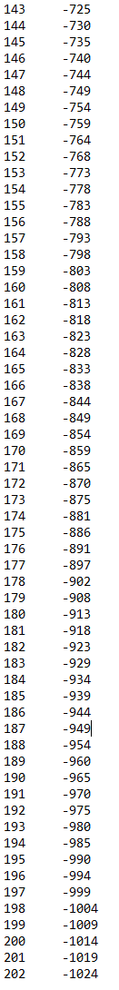
Hi guys. Today I ran a test using the A4988 driver. I took 200 steps in parallel to output the encoder values. My theory about the nonlinearity of the sensor was not confirmed. It has a +/-1 error. But this is most likely due to the 1024 steps of the encoder per revolution. Since the stepper motor has 200 steps, it turns out 1024/200 = 5.12. From here in some steps the difference is 5 in the other 6.
In the table, the last point is 202, this is because I did not write the code correctly, and the microcontroller took the steps before enabling the driver
I will try to use mt6835, it is set to 3000 steps per turn. I do not want to calibrate it, since initially I planned to use in my project a nema 34 with a force of 12 N. m. But if nothing happens with nema 17, then there is nothing to spend money to buy a nema 34))))
Ha! This works without calibrations. The first time. Apparently the library does not work very well with encoders, which have not multiples of the ratios of steps to the magnetic poles. Or the MT6701 sensors are not very accurate.
I like mt6835. It is a pity that because of the new rules ali express no longer delivers goods to Austria. And I can’t order anything else there. Including encoders:(
Are you using the driver code from the drivers library, or your own driver?
I have to think about this, but it really should not be the case. The encoder still has a fixed number of counts per revolution, it doesn’t depend on the number of motor turns. So the “zero point” should always be in the same location on the motor shaft. The electrical zero may be “between” two encoder counts, but the error (ignoring latency) should not be more than resolution/2 .
I think it more likely that is is an issue of control - resolution/latency vs the high pole count/accuracy required that leads to unstable control. Or that encoder ticks get missed - that would lead to position drift without the Z signal to correct it.
Yeah man, I hope they fix this soon…
But cool to meet a SimpleFOC user in Austria! I’m in Vienna, where are you based?
I had a similar problem with the engine from the gyro scooter. I also used mt6701 in it and it didn’t work either. I will try to use mt6835 now. I hope it will be successful
Very cool! Perhaps we can get a chance to meet up at some point.
It’s been working ok for me, in its SSI mode. I have still to test the ABZ and I2C modes… I just don’t get enough time
I tested our driver for it out today, and fixed some more bugs. It is working well for me now in SPI mode for reading the angles. I’ve committed the changes to the dev branch of our drivers library.
I have not yet tested setting options or doing the calibration… I assume you’re using the ABZ mode?