Successor to the Lepton (apologies if premature)

I was biting my tongue and not saying anything because I didn’t want to distract from efforts on the Lepton. However I’m impatient, my supply of low cogging motors just evaporated and this reaffirms the importance of a good quality, general purpose motor driver, which I could at least have some hope of implementing some kind of anti cogging feature in.

Given the issues thus far with the Lepton, I have to admit it does not look like finish line of my journey that I am frankly way over budget and overtime on to begin with…

The flash memory is really small, and there are a lot of issues with compatibility with the Arduino ecosystem.

There are a couple other minor issues, and it’s clear that the code base also needs more effort (always lots to do, no ragging on those who have already done stuff, just that still more appears to be needed).

There is no way I can economically undertake this myself, and it’s not sensible to try. I propose a concerted community effort to make a system that is a successor to the Lepton. I am thinking:

  • the RP2040 could be a good choice? JLCPCB has it in stock. There is already some effort that has been done on getting SimpleFOC to run on it, apparently. It is well supported by arduino, the RBPI foundation is good stuff, it will be around in the future, is easy to interface to and program. It’s fast, has lots of memory and can be used in many other contexts. To be honest, for my project I have considered using a Pico board and just making a custom 6 pin pwm stage and encoder and soldering the stuff all together, but it wouldn’t be any better and we do have the capacity to get custom boards made relatively cheaply.

  • I would make it so you can highjack the PWM stage if you want. Right now I really wish I could do that so I could test and debug things. Also the PWM stage has other uses, if the board becomes common it would be best if it is multi use.
    -I would break out more of the microcontroller pins, they might be useful for someone.

  • I would use standard 2.54 mm pitch connectors, I know they take more space, but you can use dupont connectors, screw terminals, some kinds of molex, we could even make it so it plugs into a solderless breadboard (two breadboards side by side is a good hack for accommodating very wide boards). That really helps with prototyping and getting things done quickly.
    -have at least one indicator LED for debugging and end use. People are going to be customizing the code and using it in a larger context to make what they need.
    -someone suggested making it so you can flood certain areas with solder manually to reach the potential that the mosfets have. If things can be arranged so a tinned pad is the top side of the relevant areas so you don’t even have to scratch any stuff off that would be awesome.

-The Mosquito has a spot on the back for a magnetic angle sensor. Valentine noted the magnetic field of the high current could interfere, however I think that it would be very small at low currents, so it would be good to leave some pads for an angle sensor, as with the Mosquito. As soon as the sensor is off the board, you need to connect, mount, the whole assembly gets bigger and more expensive. If you only need a little current, and the board is carefully laid out, I think it would be useful for some people, and having the pads there is practically free, yeah? I also suggest that the issues caused by interference of the magnetic field could be compensated for, potentially, possibly by using some kind of calibration routine, as it seem to me the distortions would be similar to cogging.

  • current sense might not be a bad idea, or at least have the pads for it. There are some great current sense ICs Also some extremely crude sensing could be done just with the ADC and a sense resistor, it seems to me this would have some uses, you can check to see if the voltage of the supply isn’t what you thought, or calculate the approximate resistance of the coils or whatever. Possibly also the inductance and other characteristics, which apparently is important in high quality algorithms for FOC control, although I don’t understand this much, I can see what happens when the figures are set wrong with the MCF8316 board I have, the smoothness and quality of the drive clearly deteriorates.

I apologize if it seems like I am bailing on the Lepton before giving it a chance, but even if it can work in a basic mode, is there room in the flash to add anti cogging features, for instance? It doesn’t seem very general purpose or future-proof.

If we come together and come up with a promising board and sensor combo, respectably compatible with the code base, I’m willing to get a bunch of them made and then mail them out for free to others who want some.
I bought some NPN and PNP darlington transistors as a super cheap power stage to try to experiment with the pico as a microcontroller quickly, I was unable to highjack the pwm stage on the lepton https://www.amazon.ca/gp/product/B07D3KP993/ref=ppx_yo_dt_b_asin_title_o00_s00?ie=UTF8&psc=1

I don’t really know anything about it, but the specs and price do look good.
Alternatively, I think this is a drop-in replacement with 128KB flash, 36KB RAM, although it costs a little more STM32G071GBU6 STMicroelectronics | C529347 - LCSC Electronics

Not quite sure what you mean by this… just adding 2.54mm pins connected to the PWM outputs so you can monitor what’s going to the gate driver inputs? Or would there also be a way to disconnect them from the gate driver?

That was me, and copper bars are a lot better than solder. Resistance of tin is about 6.5x higher than copper. I assume you’ve seen my version of the Lepton? It has areas of solder mask removed for this. In EasyEDA, you just add rectangles or solid regions to the solder mask layers. I’m pretty sure you could also copy them to the paste mask layers to have a thick layer of solder applied, giving slightly better conductivity without any manual labor. But even without that, any exposed copper will have a thin coating of solder from the HASL (hot-air solder leveling) step of the manufacturing process. And if you plan to solder on copper bars, then it’s better to skip the paste mask.

I tried to design a version with current sense, but it was difficult and increased the board size and component cost by a lot. And there will be places where the PCB copper has to carry the full current, so the copper bars don’t help much. Better to use a 4 layer board. And in this case I would also recommend using six 3x3mm MOSFETs instead of three SE3082G. That would make it more future-proof, since there are no substitutes available.

But without current sense, SE3082G is uniquely suited to the copper bar current-boosting technique, because you can solder the motor wires directly to the output pins, which are internally connected to both MOSFETs. Then there is no point where the PCB copper has to carry the full current, so you can theoretically use the full power of the MOSFETs (realistically I’m hoping for 40A).

Interesting. Hm, I think it may be reasonable to go for the SE3082G, it is wise to future proof as much as practical but we can have a multiplicity of designs, since having custom boards made from a design is only a couple clicks. Thus, it is mostly about the design effort and compatible components, and compatibility with the code base.

Sensor, MCU, code, PWM driver and yes, finally, the actual mosfets . I think it’s fair to argue the actual mosfets are the easiest to replace and rejigger. The combo of MCU, sensor and pwm driver is harder to cook up, and making sure the MCU has it’s oscillator, and we avoid noise issues and so on. Any on board regulators.

I personally only need like 1 amps max, actually, so I’m not super keen on spending time and money achieving high currents, but I am game for paving the road ahead.

Why is current sense expensive? I was under the impression the ADC could be used with a current sense chip. It could be used on only one lead of the motor, perhaps, just to provide measurement and monitoring. I don’t get why that is expensive?

It seems like it might be advisable to get rid of this buck regulator, what would be really nice is a multiplicity of charge pumps to provide the various on board voltages from a wide range of input voltages. Buck regulators make electrical noise, I have read, I would not be surprised if that is what is responsible for messing up I2C on the lepton.

I am not keen on these STM32 chips, this one one the lepton requires special hardware to program it, it’s not compatible with arduino properly, it is dependent on proprietary software to program it, not good. If the pico is fast enough and good enough (is it?), why in the world use something like that?

By highjacking the PWM stage, I mean you can’t buy a decent 6 pin pwm stage board right now, or indeed any high side mosfet switching boards. Being able to interface to the inputs of the fortier driver is what I want. The MCU can be programmed to be high impedance on those pins so there should be no need to cut traces or use jumpers to disconnect it. You just need a row of 6 2.54 mm pitch through holes to get there.

What about the currently available boards is not meeting your needs? Looks to me that Lepton is developed for integrating into a product, i.e. program once and be done, and the load is large (from documents I see around here people say something like 10A give or take). Needing to take extra time to setup or program is fine in the case where you spend a lot of time on development but then when it comes to producing many items, everything just works. Lepton does not look like a development board to me although I guess you can use it like that.

1A is a pretty small load, you can even do that with fully integrated drivers, no need for external MOSFETs or anything depending on your use case. How many motors and at what voltage? I don’t see why the boards that you can buy / assemble today are not working for you.

STM32 is pretty standard uc family for anything beyond hobby grade projects, it is widely used in industry. SWD is a reliable method to program it and the programmers are cheap ($15) and you can even make them yourself. People have reverse-engineered it and it is not going away anytime soon. The debugging option for STM32 is what makes it such an easy chip to work with and creates a very strong use case for serious projects. CUBE IDE is worth checking out and makes using the IC a breeze.

What is “6 pin PWM stage board”? Is the reason you want that chip because it supports HV for motor side? Or what about that chip puts it on your wishlist? Is there any reason to separate the driver from the MOSFETs like you are suggesting?

You are thinking old paradigm of large capital investment then making a ton of identical products. The Pico board, for instance, and many other open source and other projects like Micropython, and indeed Python in general, are about moving towards an approach with lower capital intensity, and using the same or similar building blocks for dev as production. This lowers capital cost. I’m not making thousands of units, I would be lucky to sell a hundred per year. I can’t afford $2000 in development costs to deal with complexity that doesn’t really help anything.

Right now, I have already spent 4 days trying to get the lepton to work, without success. At 200 bucks a day for labor, rent and so on, that’s not cheap. It makes sense to omit a usb connector or TTL-usb converter or some other things from the board, however the paradigm of a dev board vs. a production board does not necessarily make the best approach for a lot of things.

STM32 has not proven to be easy or straighforward, and as I mentioned, it is all proprietary. It is also poorly supported, as mentioned. The RP2040 has just as good debugging support. I see no reason to stay mired in proprietary, capital intensive, hard to use stuff.

Standard, compatible, interchangeable, open source building blocks are a good idea, that’s what I am trying to steer towards. I think this is the wise way to develop technology, and this is how the tech dev process tends to go on a large scale and long term, simplifying and modularizing, abstracting, making a sound foundation that can be efficiently used and stood upon. I’m sure you could have said something similar about assembly and other chips back in the day.

But that’s more of a philosophical discussion, I think it’s pretty clear the simplefoc project and the arduino board are neither dev boards nor are they production boards. Indeed unfortunately due to the slow speed of the arduinos, they are neither and yet expensive and not good for that much at all. It would make sense to make something to superceed them.

I’m watching this thread with great interest. I’m really busy and away so I can’t contribute now.

Cheers,
Valentine

Just to chime in here, I would consider the following points:

  • while RP2040 MCUs are inexpensive, they also need more supporting components than STM32 MCUs, like external flash memory, which offsets some of their price advantage.
  • This, and the fact that they come in exactly 1 configuration in terms of pinout also makes them a little harder to work with than STM32 MCUs, which really integrate everything and come in thousands of configurations to meet your needs.
  • RP2040 has sufficient PWM for motor control, but actually its motor control features are weak compared to even the G0 or F1 series of STM32. They can’t even begin to compare to the powerful F4 or G4 MCUs in terms of what they can do with motors.
  • STM32 has excellent ADCs, and their implementation shows they know what is needed for motor control. RP2040 has a terrible ADC, which is pretty much useless for motor control.

In terms of the open source side, while STM32 is a proprietary product, they will give support to any customer, and their documentation and resources are excellent. I don’t agree that they have poor support.

For example, they support an official (and open source) STM32 Arduino framework which is updated regularly and works very well.

On the other hand, RP2040 may be open source but their Arduino framework hasn’t been updated for ages, and they don’t really support it so users, in their desperation, have to make their own versions.

So I would say the picture isn’t really so clear here in terms of the MCU showdown STM32 vs RP2040, and if you take into account the application we’re interested in – motor control – then for me at least STM32 is a clear winner.

As someone who deals with this professionally I’m not even sure why the 2040 even exist, but that’s my personal opinion. I was really excited when it first came out, but then not so much, especially when the ADC silicon bugs appeared. Even the simple and common F103 which is nearly 20 years old is thrashing the 2040 as far as functionality. The G431 is probably the best all-around MCU if anyone wants to do anything motor control related. As @runger noted the ST Micro support for Arduino is impressive, it’s very rare for a large company to actively contribute in such a manner.

I don’t know why you dislike the lepton, I didn’t get to try it out yet… maybe I’ll find out :slight_smile: but looking at Deku’s posts it seems to me that it is quite useable…

I think you’re having a similar experience to myself, by which I mean that you’re not finding a real “market fit” in terms of the ESC you would like to have and use. I’ve spent 2 years on it now, and I’m still not quite there :smiley:

I think part of the problem is that motor control sounds specific, but actually the range of applications is very wide, and therefore also the choice of motors and possible drivers. Many commercial products are quite niche, or aimed at purely business customers with correspondingly high prices. So it’s hard to find off the shelf parts that suit one’s maker project and budget.

The driver stage and the mosfets are really more closely linked. It’s more easy to separate driver and controlling MCU, as the interface is usually a digital “6-PWM” one. The analog side of current sensing makes things a little more complex still, so really I’d say it’s best if the whole driver stage including its controller is designed together “in harmony”.

But really this is the difference between the “shields”, like SimpleFOCmini and SimpleFOCshield, and the “drivers”, with on-board MCU and communications interfaces like Serial, CAN or I2C.

On the one hand the chips needed (current sense amps, shunt resistors or hall sensors) tend to be more expensive than, say, cheap mosfets, and on the other hand since this is analog design choosing high quality (and hence expensive) components will affect the quality of the result.
Also, I would expect this section of the design to need the most tuning and iterations, making it expensive in development too.

Charge pumps would not normally be used for this purpose, I think. Or they’d be called step-up converters in this application. Anyway, this is what DC-DC converters like buck regulators and related topologies do… and they’re very efficient at it, you can expect 80% or even better efficiency from a simple buck converter. If you can find the space I think having a buck converter to produce the logic voltage from the input voltage is really convenient. After all, you will need power for the MCU from somewhere.

What input voltages do you envision supporting? It makes a big difference to the design.

But dealing with power is a major topic in any case, many engineers spend their whole careers on it.

It’s optimised for size… and uses a very low cost STM32. RP2040s also need USB circuitry to flash them via USB, and conversely, many STM32 MCUs will support USB flashing from their built-in bootloaders in the same way a Pico does.
If programming via USB is the aim, there are several MCU types which can do it out of the box, including STM32s.

It has better Arduino support than the Pico, and it has open source toolchains as well as several proprietary ones.

Pico is a very nice MCU with some very nice features (like the PIO) but in terms of “MCU hierarchy” it is at best mid-range. It has two cores (that’s cool!) but they’re only ARM Cortex-M0plus running at 125MHz (fairly fast for M0).
STM32 has Cortex-M0 MCUs like the G0, but also Cortex-M4, M4plus, M7, H7 and more… ESP32 has dual-core RISC-V based processors running at 240MHz…

There can be lots of good reasons to use either type of MCU, but for motor control I’d generally say STM32 will be better.

That’s the “shield” type approach. The SimpleFOCmini is more or less exactly this, just not with a fortior driver.

2 Likes

hm, ok, points taken. However, we definitely need more ram and flash. The lepton can’t even run the commander. I don’t know what role it’s supposed to fill, but I think there are many applications in the community where we are going to want more wiggle room. And we should pick one good MCU and make sure it’s working.

When serial doesn’t work, I tend to assume it’s not very well supported. That seems like basic stuff.

I agree an integrated board makes much more sense than a shield, or as they are called for Picos, HAT. The MCU is monopolized anyway. All the additional cost and complexity doesn’t help much. As we have seen, mixing and matching code+MCU+driver+sensing is not easy and not that helpful. A small selection of quality motor drivers would be much more useful than an enormous number of possible combos, none of which can be made to work without a great deal of labor input. A small selection starts with at least one. I don’t believe the uno shield+an uno is really good for much, although it was a good way to get the ball rolling, now the time has come to keep it rolling and achieve a second milestone, I believe.

So what would be a good MCU then, within the STM32 class? It’s gotta have some more space. I would rather just use the microcontroller from the blue pill, even the dev boards are only 3 bucks. I know you mentioned the supply shortage, but there seems to be lots for sale everywhere.

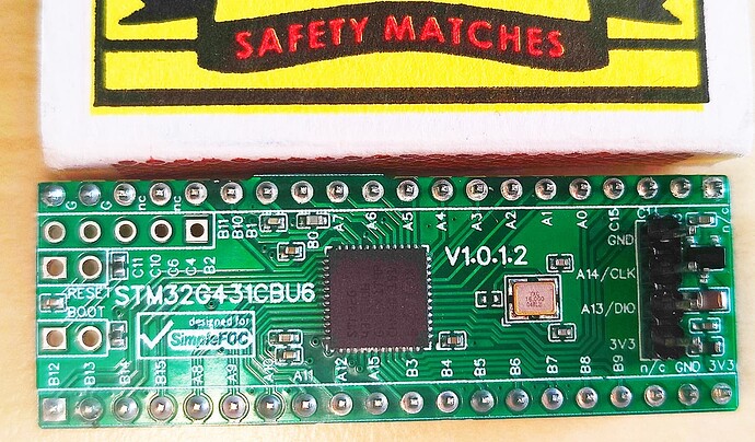
STM32G431CBU6 is your best choice.

I created this as an ultra-cheap drop-in replacement for the Blue Pill where I needed a lot more processing power and memory but exact same footprint. However, I’m at that point a little hesitant to share my designs as it appears that people expect this to be end-user production ready stuff and I started getting way too many emails about “why this didn’t work” and I feel bad becasue I don’t have the bandwidth to explain or maintain those designs.

However if you want to create your own design, this is true and tested MCU. Also this is the same MCU which is used in the STM ESC ( b-g431b-esc1 ) controller that people seem to be blowing up all the time. It’s got twice the memory of the Blue Pill and three times the processing power, as well as built-in op-amps.

That particular board cost me less than $5 if you order a very large batch.

Cheers,
Valentine

PS this is the board I overclocked to four times the Blue Pill by mistake when I was testing it and it didn’t blow up, I was quite impressed. If you are careful, lower the voltage and get decent cooling this is pretty interesting if anyone is into this stuff. I’m not sure how the comm ports would work though, I’d expect they’ll break.

1 Like

Its role is to get us poor boys up and running :slight_smile: And to educate us on how to design our own boards. And if you need more memory, that G071 I linked before will do the trick without even having to modify the PCB. Although it would be better to make a variant with the G431 Valentine mentioned, since it’s both faster and cheaper. Personally I don’t care about Commander or cogging, but do care about physical size, so I’m happy with the G031.

Regarding noise pollution, even with anti-cogging we’re still pumping out lots of 25KHz waves. Not a problem for humans, but after my experience running Valentine’s example code that sets the PWM frequency to 15KHz, I feel sorry for any cats and dogs in hearing distance. I wonder if it’s possible to make a truly silent driver.

Regarding cost of current sensing, it doesn’t look as bad as I remembered. DRV8323 is around $4, high precision resistors are under $0.10, and and 4-layer on JLCPCB doesn’t add too much, so you’ll probably end up around $10 per board.

I imagine some of the tech from variable frequency drives and true sine wave inverters could be applied to further reduce the noise, but my crude understanding is that the induction of the motor coils smooths out most of the stuff. Even if the PWM frequency is in the audible range for a human, it is a problem for me but it’s not painfully loud or anything. Some SimonK escs use like 8 khz or something, I have tried messing with them. Also higher frequencies get attenuated much more effectively by all kinds of stuff, so I think our furry friends are probably ok.

Hm, this sounds like progress.

In a way I dig your position Valentine, however I think a better solution is collaboration. The very fact that it is not trivial even for you to produce a ready to rumble desing is precisely why a design that is vetted and evolved to smooth out issues is needed. Leaving everyone to try to roll their own is impractical, people only produce very crude designs that are of little to no use for anyone else, and spend great amounts of time and effort doing it.

I don’t see the point of educating people to make their own boards and then somehow no one ever collaborates to produce a good board. To me, Open Source is basically a method of collaboration over long time scales and large distances, and with tight budgets, usually.

Sooner or later, the sensible road clearly leads, imo, to at least one flagship combo, ideally an actual board.

A couple bucks extra for the MCU and optionally current sensing (or just the real estate on the board, leave the chip off and save your $4 if you don’t need current sensing, I don’t think I do but it remains to be elucidated) sounds like a bargain when the other boards kicking around like the Odrive are like $150 USD or somesuch.

Also given the time and effort to roll your own, especially when it’s not your forte, a couple bucks for some components for some extra ram and flash is a really good deal.

It think the PCB is going to have to be changed anyway, though, the interference with the I2C I don’t claim to understand, but I have communicated over I2C over much longer distances and it appears to be serious.

BTW my experience was that the uno+shield+as5600 board was like $45 USD, there were people advertising for less but they had various downsides. And I don’t think that’s helping support the project, it’s like aliexpress (the official store was out of stock). So I really don’t see how it could compete with a proper flagship board, even if you go for the better components. Above all the uno is way too slow.

You are absolutely correct, the G071 has twice the memory and exact pinout and footprint. You can do this during order time and directly replace in the BOM. That’s an excellent point. The difference would be only about $1. When I originally designed the Lepton I aimed for rock bottom price of everything and G071 wasn’t even in stock.

1 Like

STSpin32G4

Relatively affordable w. integrated driver. What’s not to like. I’m sure you have noticed the “Hat” or modular approach I have been targeting lately.

Regarding the modular approach, one argument for doing that is to have kinda separate thermal zones. Also, by separating the MCU and the power-stage the footprint can be stacked horizontally.

I have PCBs inbound for the STspin23G4. If the design works out, there is a good foundation for further colaboración.

Edit: hmm in transit CN still. Being patient…

Another argument for the “hat” is naturally the fact that users can customize their power stage for whatever purpose they need (within the constraint of the FET driver). In reality what I propose is a format, a pin-map for the MCU w. Integrated driver “hat”.

What’s the matter ! The hatter is the matter

:slight_smile: I’ve. been working on my STSPIN32G4 design too… but I’ve redone it a little, and now have a version with and a version without CAN-BUS. The chips input voltage range of up to 75V gives you a lot of room to play with there, but the built-in buck converters can’t supply enough current. So that means you have to put your own buck converter on there in the end if you have any kind of current draw.

So I’m kind of undecided which way to go and what shape this board should take…

I’m involved in several collaborations to make motor driver boards, and I think there are several more “in progress” by various people here.
Maybe this whole community is a collaborative effort in that direction?

I honestly think it just isn’t that easy. Lets consider some dimensions within which we have to make choices to optimize the design:

  • input voltage (10V is quite different to 100V)
  • current capacity (low power very different to high power)
  • performance / efficiency
  • motor driver features: braking, protections, high speed PWM, current sensing, voltage sensing
  • cost
  • manufacturability (eg. 8 layer vs 2 layer, feature sizes, copper weight)
  • parts availability
  • interfacing (CAN bus, USB, SPI, I2C, Serial, Programmers)
  • ease of use
  • software support

Which will you focus on? I think if you try to get a “good mark” in all these points, then you wind up with something like ODrive, and at a similar price-point :wink:

1 Like

Enough for what!? It should, hopefully, provide enough current for the FETs otherwise it really doesn’t make sense?

Also, what limits the buck?

I’m just excited to get testing :grin:

Well, the 3.3V output supports max 150mA.
But for example CAN controllers can draw 200mA or more (if CANH/CANL are shorted for example).

The drive voltage is variable (can be set via the chip’s internal interface) but it’s only intended for the FET drive and internal use. You can’t take a lot of power there. But certainly you would expect it to support the motor driving, I didn’t mean to imply it didn’t have enough for that.

But if you want some LED lights, a 5V or 12V cooling fan, or even CAN-bus (and stay within spec) it looks like extra buck converters to me. Which is annoying.

Ok, you may be right. Will be interesting to test. Since my current focus is USB connected, I could draw some 5v from there but for a fully battery relying setup without any other power source, that could be a issue, especially power-hungry Bluetooth or WiFi transmission.

Anyways, I agree with you. Lots of considerations for various use-cases, target voltage, power rating so on and forth. Exiting times !