I’m not following you here.
Ohm the great wizard
Just contemplating why one would have separate MCU power from Analog power. Then it hit me, since the digital power may radiate unwanted noise, hawing the Analog Power separate and filtered with appropriate caps, may improve the analog domain. Just some random thoughts I wanted to share.
Regarding the Inductor for the Buck converter, there are some hmm… not so specific info in the ST reference design (BOM). In the schematic it clearly says 18uH inductor, while the BOM list a 15uH inductor, so im trying out the 15uH just because it has higher current rating. I guess the buck converter will try to maintain / hit the target voltage no matter what, and adjust the switching accordingly.
All components has been ordered. Working on a small combined panel. Lets do this !
1 Like
I’m going in for the Mouse bite ![]()
CUBE_MX Project and last minute change:
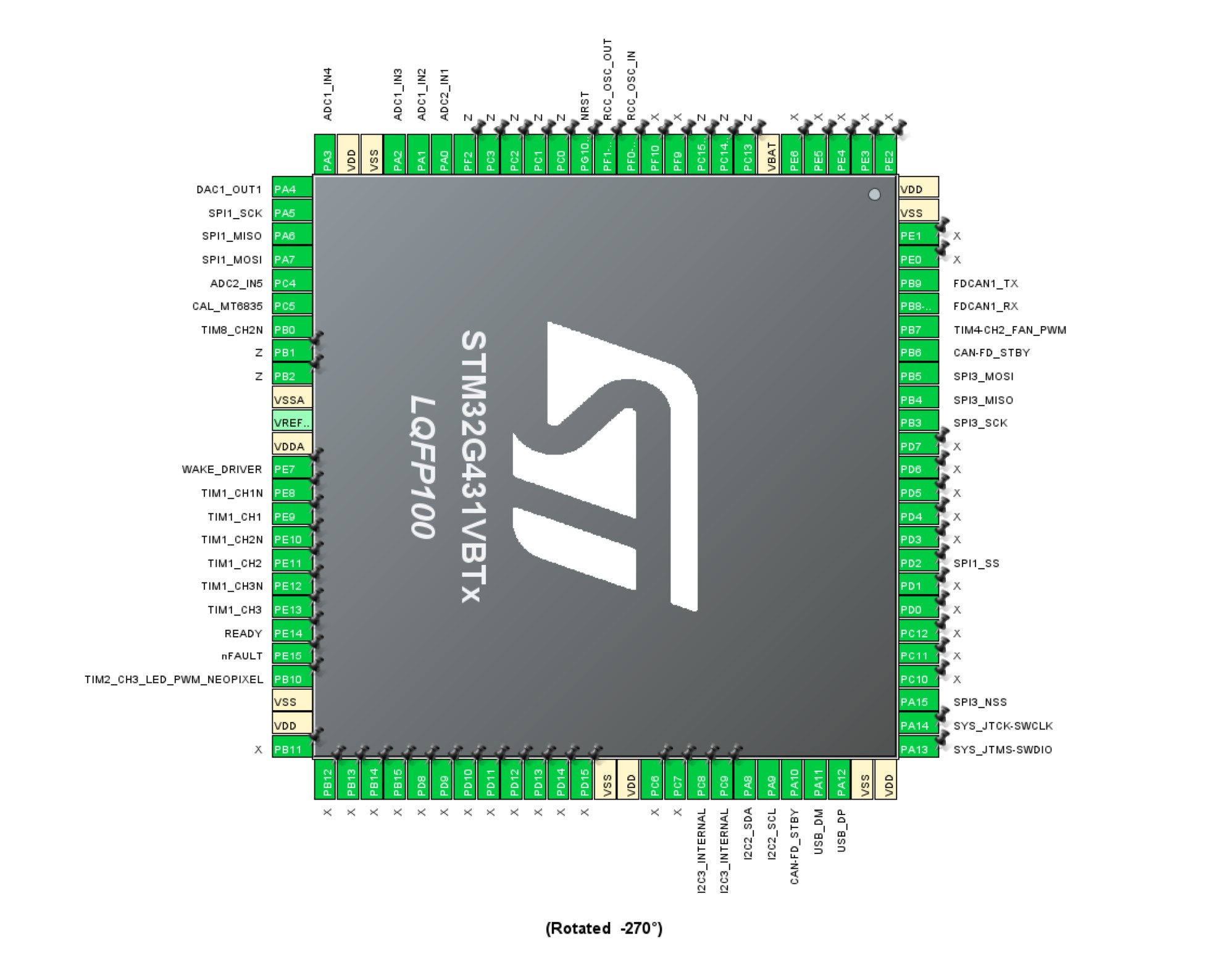
Good thing to always be patient when designing circuit boards. There always seem to pop errors up here and there. By completing the CUBE_MX project I found it is necessary to move the NEOPIX LED pin to PA10 on TIM2. Hawing that LED on a separate timer is crucial to make it work on STM, since those LEDs need a 800kHz PWM signal.
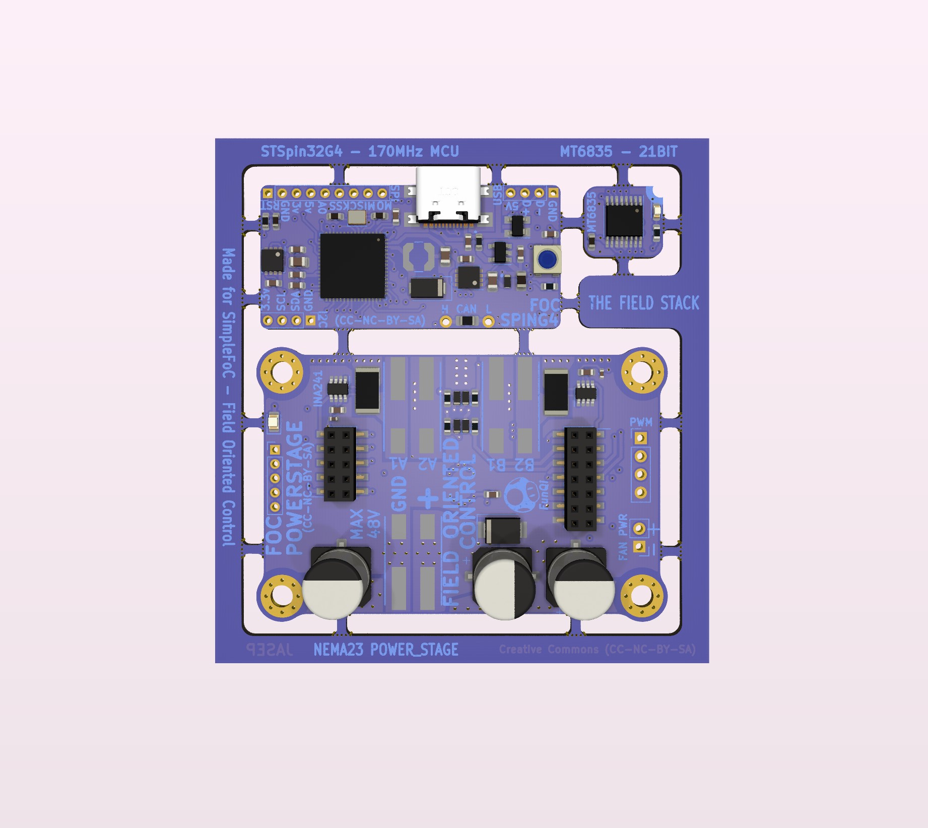
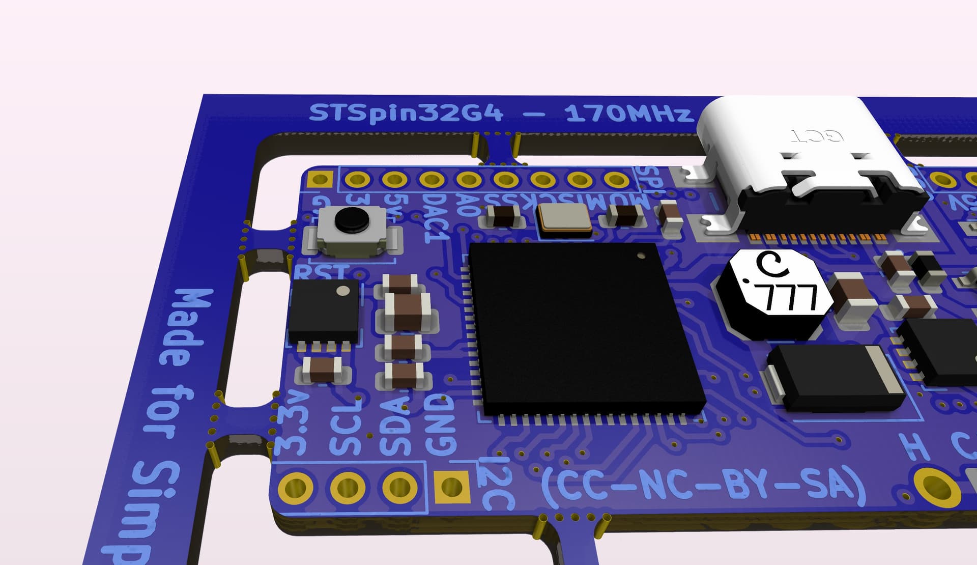
Found room for a small Switch for the RESET pin, this way the DAC1 pin can be routed to the pin_header row. Not sure when to use the DAC in a motor controller, but maybe it is useful for some arbitrary purpose. That pin can also be Analog input, or perhaps function as a step/dir input.
Im not using all the pins on the STSPIN32G4, so those not in use is marked Z. Pins marked X is not available on the STSPIN32G4 (Combined MCU and 3phase driver).
Edit: One use_case for the DAC, I just thought of, is for a speedometer on the handlebar of eg. an electric bike, if for some reason it is analog.
Which code are you using? Is there a STM32 timer-based Neo-pixel driver? I’d be interested!
The NeoPixel’s annoying 1 wire protocol works at 800kHz, but the encoding is based on varying the duty cycle to encode the bits. This is non-trivial to implement with timers, which is why I think many drivers use the SPI peripherals (which naturally have the ability to shift out data bit-wise onto pulses) to emulate this encoding.
I have not used them on STM before, but from this tutorial is look possible w. TIM2
Although annoying they are quite powerful RGB diodes. Signaling or some low level HMI is suddenly quite simple. Red = Error! Something is wrong. Off = saving power when everything is OK. Green Blink = Got it! Message received. Blue = ? (not sure)
Nice! I will bookmark that one ![]()
But unless you plan to implement that code into your firmware, I would check how one of the common Arduino Libraries does it: Adafruit NeoPixel (the standard) or FastLED come to mind, but there are others… might turn out they need a timer, but might also be they want an SPI pin…
Yes, that is the plan. Why not ?
They also give the RGBW LED sample. Pretty neat IMO. Maybe the white could be like constant ambient on light, set to 20% intensity or what ever the user want I guess. Some folks like it when they change color like RGB led´s on RAM blocks.
Well, because in one case you have a finished, widely used and therefore tested and peer reviewed library you can just install with the library manager, and then write things like:
strip.clear();
strip.setPixel(1, strip.Color(255,0,0)); // set pixel #1 to red
while in the other case you’ll have 100s of lines of HAL-based STM32 code to integrate into the program by yourself, and as far as I can tell, no convenience functions, just the ability to set pixels from a memory buffer…
its much more work this way, but that may be part of the goal - it all depends what your aim is. ![]()
That is true, but I do not think the Adafruit NEOPIX Arduino lib has STM support…
If some nerd comes along with the time at some point and wraps it into a lib. that would be awesome.
SPI2 MOSI is on USB-DM pin. The other SPI ports are taken. I suppose it must be MOSI (MasterOut-SlaveIn)
I must say, this LED stuff is naturally low priority, as long as there is proof-of-concept w. TIM2 im good.
Yeah, I remember looking into it and being confused about how the STM32 worked… it not being supported would be a good explanation ![]()
if there is no ready to use library, then of course this is an excellent solution!
Mkay, so it should work w. the lib. I will just keep it on that pin w. TIM2 just in case.
Seems its really a “gap in the market” ![]()
Keep in mind the various neopixels are mostly 5V logic, officially. I’ve seen people drive them directly from 3.3V, but YMMV…
Yes, I will try with 3.3V. If it turns out to be a issue I will give it a level shifter / Schmitt Trigger.
I think to remember that the datasheet says 3.6V to 5.5V or something like that. So 3.3V is out of SPEC but still close. If it works it works. Maybe the brightness is higher w. 5V. I do have 5V VBUS right next to it, so using that is really not an issue apart from the level shifter thing.
Maybe I have got this backwards. Maybe it can work w. 3.3V signal and 5V power ?
No, you should really power them from 5V. Otherwise they can be unreliable, and the blue led will be weak, the colours will be off.
The question is whether you can run the logic (DIN) from 3.3V, and here some people do, but I’m not sure it’s good. It depends on the LEDs, but if they have “HIGH” as VDD * 0.7, then that is already 3.5V… if the 5V is a little more like 5.5V, its 3.85V… that’s the kind of area where individual boards may or may not work, depending on temperature for example. I would not do it.
But really, I think it depends on which LEDs you’re using. I’m sure there are ones designed for 3.3V by now?
I did try out driving a 5V NeoPixel using open-drain mode on a 3.3V logic (but 5V tolerant) pin - that worked for me.
I suppose the correct way to drive them is with one of these. I will just tie OE to 3.3V. Non-inverting 3.3 to 5V line driver. I like the X2SON5 package, although it is tiny.
Single supply translating buffer/line driver; 3-state (mouser.dk)
Hmm…SOT-353 package is actually possible to solder. 0.8mm x 0.8mm (X2SON5) is not.

Edit: Since I already ordered the TXU0101 1bit dual-supply level shifter for the FAN PWM I will go ahead and use that. Maybe there is a advantage to dual supply as well, it looks like it could be isolated. Unfortunately, now that I have decided to do this properly, and I will, the datasheet recommends small 0.1uF caps on the VCCA and VCCB input’s.
I think I will break out the Data-Out pin on the NEOPIXEL, this way the user can potentially connect a string of these LEDs, controlled by that one level shifter/trigger.
I have seen multiple ESP32 projects where they add a neopixel/digital led to the board, feed it 5v power through a diode so it becomes 4.3V and then 3.3v logic seems to work. The neopixel will shift the signal higher for output so it’s a commonly used strategy if you want to control a string of neopixels/digital leds to add one on the board with the diode trick, route it’s output to a header with ‘normal’ 5v power and use it as a poor mans level shifter and diagnostic led.
edit: found a hackaday post on this trick
I did see that hack/trick, Im ok using the Schmitt-Trigger even though it does ad a small cost.
Just finishing up the Panel. I thought it a good idea to use the “frame” to make a SWD POGO pin programmer adapter for the ST-Link 2x7pin 1.27mm pitch header/cabel. Yet another cost, but I had to order some stuff I forgot, and just as well get free shipping. I’m including the reset pin, since the SWCLK is in use as TIM8_CH2.
As I understand it, it is possible to set up the ST-Link to use the reset line, when connecting the target?
This way I have:
- GND
- RESET
- SWCLK (TIM8_CH2)
- SWDIO
- 3.3V
