Hello,
I have used the following code for my G431B-ESC1 board:
// Open loop motor control example
#include <SimpleFOC.h>


// BLDC motor & driver instance
// BLDCMotor motor = BLDCMotor(pole pair number);
BLDCMotor motor = BLDCMotor(7);
// BLDCDriver3PWM driver = BLDCDriver3PWM(pwmA, pwmB, pwmC, Enable(optional));
//BLDCDriver6PWM driver = BLDCDriver6PWM(PA8, PC13, PA9, PA12, PA10, PB15);
BLDCDriver6PWM driver = BLDCDriver6PWM(A_PHASE_UH, A_PHASE_UL, A_PHASE_VH, A_PHASE_VL, A_PHASE_WH, A_PHASE_WL);

// Stepper motor & driver instance
//StepperMotor motor = StepperMotor(50);
//StepperDriver4PWM driver = StepperDriver4PWM(9, 5, 10, 6,  8);


//target variable
float target_velocity = 1;

// instantiate the commander
Commander command = Commander(Serial);
void doTarget(char* cmd) { command.scalar(&target_velocity, cmd); }
void doLimit(char* cmd) { command.scalar(&motor.voltage_limit, cmd); }

void setup() {

  // driver config
  // power supply voltage [V]
  driver.voltage_power_supply = 12;
  // limit the maximal dc voltage the driver can set
  // as a protection measure for the low-resistance motors
  // this value is fixed on startup
  driver.voltage_limit = 1;
  driver.init();
  // link the motor and the driver
  motor.linkDriver(&driver);

  // limiting motor movements
  // limit the voltage to be set to the motor
  // start very low for high resistance motors
  // current = voltage / resistance, so try to be well under 1Amp
  motor.voltage_limit = 1;   // [V]

  // open loop control config
  motor.controller = MotionControlType::velocity_openloop;

  // init motor hardware
  motor.init();

  // add target command T
  command.add('T', doTarget, "target velocity");
  command.add('L', doLimit, "voltage limit");

  Serial.begin(115200);
  Serial.println("Motor ready!");
  Serial.println("Set target velocity [rad/s]");
  _delay(1000);
}

void loop() {

  // open loop velocity movement
  // using motor.voltage_limit and motor.velocity_limit
  motor.move(target_velocity);

  // user communication
  command.run();
}
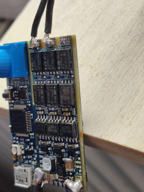
Once I connected 14V to the input the outermost phase (from the daughterboards view) burned both mosfets in a big smoke cloud. One of the motor wires even desoldered in the ~2s it took me to disconnected the power supply again.
What did I do wrong? I’m scared to try my other ESC since they are hard to get here.
The pins seem to lign up with the documentation from STM. I checked the aliases used and have noted the pins in the commented out 6PWM constructor above that.
Motor is an Emax Eco II 2207 2400kv. Used a 4S battery.
What I’m def. doing next try is use a current limited supply and not a battery  .
.
Anything else I could check before powering up? It seems like there was a short and the timing of the phases was incorrect. Don’t really know how to debug that safely.
That motor is listed as 41mOhm resistance, which is very low. And you have voltage_power_supply set to 12V, while a fully charged 4S is 16.8V, so the applied voltage could have been as high as 1*16.8/12=1.4V, making the current 1.4V/0.041Ohm=34A. That board claims to handle up to 40A with forced air cooling, but such ratings are often wishful thinking. I’d start with 0.1V to be safe, with voltage_power_supply = 14.8. Although a current limited power supply is an even better idea.
Burning both MOSFETs of a single phase should only happen if they’re switched on simultaneously, creating a short circuit rather than sending current through the motor. But I don’t see how your code could have resulted in such a condition, plus then the motor wire probably wouldn’t have desoldered, so I would guess that the upper MOSFET in the photo isn’t actually dead.
Okay thanks for your input. I did not realize that motor was considered such low resistance. I followed the FOC tuning guide from youtube where 1V is recommended and he later goes up to 3V if I remember correctly.
I can just make out bulging on both mosfets and I think I saw smoke coming from both of them. I will try to measure them if that’s possible. Def. not plugging that in again If they where easier to get here I would buy some new ones and try to salvage it. But best is mouser with 20€ shipping on top of ~8€ mosfets. I can just get another STM devkit for that money…
I just tried my other ESC with a 12V 2A limited supply. The motor starts spinning at ~0.3V but stops when you blow at it. I’m gonna wait for my hall sensor to arrive before I do further testing.
The ESC is getting surprisingly hot @0.2A/12V. Those 2.5mOhm fets really do suck.
They even seem to have downgraded the dev board. The schematics say STL180N6F7 but I can def. make out a 3 instead of an 8. But the 130A versions seems to be basically the same with 3.5mOhm Rds On. The 130A version is 1mOhm worse. I misread.
Yeah, it’s always frustrating that it’s not worth the cost of buying replacement parts unless you plan on burning a lot of them 
What kind of motor was used in the tuning guide? 3V would be fine for a gimbal motor with high resistance. Although it would be fine on a low resistance motor too once it gets spinning. This is how the voltage-based current limiting works.
It is possible that you got a short circuit somehow. Burning in 2 seconds does seem awfully fast for 34A. But I don’t know how it would have happened with your code.
I measured all fets on the broken one with a multimeter. The 2 suspect ones measure <50Ohm. The rest is a few kOhm to MOhm depending on the pin combination.
The motor used is a hoverboard motor.
Should adding the current sensors and hall sensors protect me from burning the motor (ESC) when it get’s going? Not really that versed in the ESC world… Just trying to get the motor to turn slowly and reliably. I know 2400kv is not really suited for that purpose but that’s what I have.
Turning slowly may not need anything more than what you already have. The back EMF will never be very large, so even if the motor is stalled the current won’t rise significantly, so there’s no need for current limiting. And open-loop velocity mode is less efficient and gives less usable torque, but if you’re running on wall power rather than a battery and have a light/steady load that doesn’t destroy itself if it misses a step, then that may be ok.
Buy a gimbal motor if you can. It will be less touchy, and use more voltage/less current so the ESC won’t heat up so much.
You’re trying to use 6-PWM code, but I only see three motor wires?
Is that possible?
I’m a newbie too, so forgive my ignorance if this is a common setup.
@o_lampe 6PWM means you have independent high & low side control for each phase.
With 3PWM drivers, the PWM state input to the driver switches high or low for you and requires some additional logic (handled internally inside the driver). In general use there is not a big difference here, but 6PWM would be required for some more advanced applications where you need more control over the phase state.
1 Like
That’s interesting to hear. I thought low rpm required hall sensors since the risk of a stall is pretty big.
I have a meter long model boat with 2 of the 2207 2400kv motor and want to run on a 4S battery.
I have some normal drone esc right now but the dont start until a few hundred (maybe even above 1k)rpm which is way too fast for the boat. This is why I’m looking to run them slowly and with a decent amount of torque. I have pretty small props and the motors don’t seem to struggle but they also won’t start without a load on low rpm with the other ESC.
I could get it to spin very slowly with Simple FOC but the torque is just not there to even get the props turning in the dry so I don’t have much hope for in the water.
This is not supposed to be a speed boat. Just a little faster than stock (brushed).
Ok, definitely add the sensors then. I was imagining something more along the lines of a clock that just turns slowly and with minimal load.
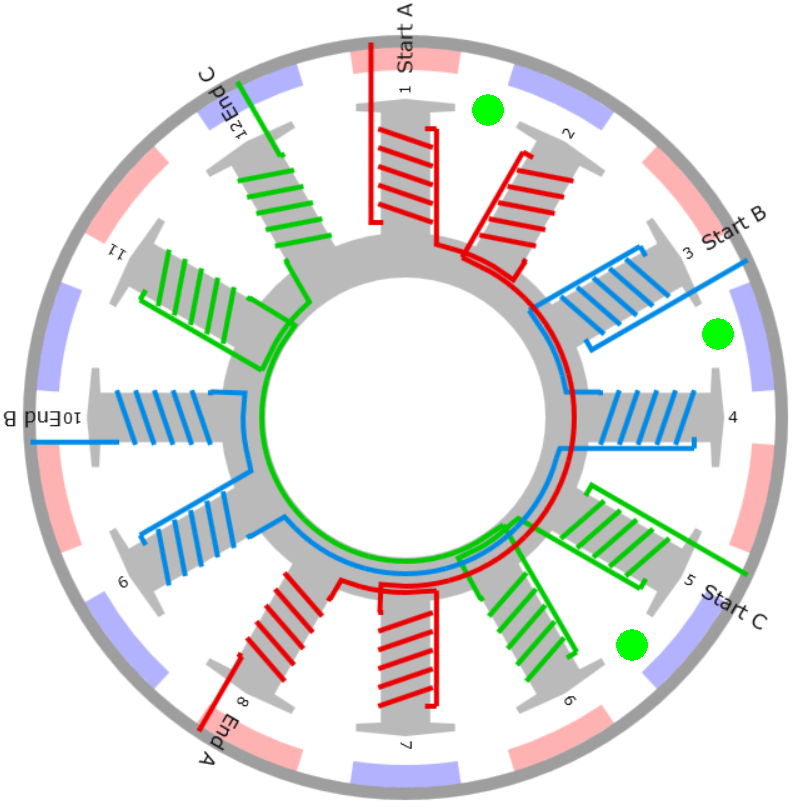
Adding hall sensors to small motors like this can be pretty tricky. You should have one sensor at the center of each phase. 12N14P makes it relatively easy since teeth are wound in pairs, so sensors go exactly half way between teeth. But you do have to identify which teeth are same and different phases, else you have a 50/50 shot of getting it wrong.
Sorry to hear about the burn out, it’s always a drag to loose a component. You can just use a wall wart or something, but they tend to shut off entirely if overcurrent occurs. A CCCV bench supply is about $100 and a good investment if you do this kind of thing a lot.
I think you chose a good board and should be able to do what you want, but I would say that if you don’t have special requirements there are already stock boards that should work for this type of thing…
@Anthony_Douglas
I have searched the web and could only find sensored escs for xas that go up to 2S or ones with up to 6S but for ~150-200$ which is a little over my budget (<100 for 2 ESCs).
I also like to tinker and this board seems perfect. The quite big temp increase with low current worries me a bit. I have some generic 45A ESCs right now and they stay stone cold. Not sure how they do that considering that I’m pushing way more than the .2A i was on the bench. And the fets are probably nothing special. If all fails i will add water cooling. A boat enables that quite well.
@dekutree64
Thank you for your confirmation that’s about exactly what I planned. I wanted to position the hall sensors either underneath the motor bell and if i can’t squeeze them there I wanted to go for the outside mount that has been trialled by some folks in some RC forums. 17.14 deg spacing should be correct for that if I’m not mistaken. Just waiting for my hall sensors to arrive. Ordered over a week ago and they should be posted domestically. Not sure what’s taking so long. Predicted delivery is Tuesday.
Are they linear halls or digital/latching type? Here’s a thread about using two linear halls spaced 17.14 outside the rotor 40 cent magnetic angle sensing technique - developement - SimpleFOC Community
But putting the sensors outside the rotor only works with low quality motors that leak a significant amount of magnetic field. Most of the motors I checked gave almost no signal unless I got the sensors toward the inside, under the edge of the rotor.
Sanding the lip off the rotor so the bottom edge is nearly flush with the bottom of the magnets can be helpful, so you can get the sensors closer to the magnets, and to allow more field leakage for them to detect. But can mess up the balance a bit since the blobs of balancing compound are often placed there. But that’s only an issue at high RPM.
Two digital halls spaced 17.14 degrees could possibly function as a quadrature encoder using the Encoder class, but with only 4 counts per magnet pair it may not be able to move. SmoothingSensor could extrapolate it to a smooth signal, but only after it gets going. Probably wouldn’t be able to get much better performance than a sensorless ESC.
I have a ton of 49E linear halls if you need some (it was about the same price to buy 10 or 100). And only costs a stamp to mail a few in an envelope
I wondered where the 17.14° came from and the formula behind it seems to be:
360°/3 (phases) / 7 (polepairs)
Now everyone can calculate the right angle depending on their number of magnets.
@o_lampe
I think you got it. For more info you can have a look here: Rocket Science: Hall Effect Sensor Placement for Permanent Magnet Brushless DC Motors. I found it to be a great explainer.
@dekutree64
I also go 49E halls.
Interesting that you think there will be minimal leakage. I will definitely try the bottom mount first. There should be just enough space and I’m designing a 3D printed mount anyways so i can as well try to incorporate the sensors.
I also don’t quite geht why only 2 on the outside when it basically has no benefit. 3 would be just as easy to mount and should give full benefits (if there is enough of a magnetic field)?
Since I have got some people here I will definitely keep you updated what works best and how it performs. Might need to try the outside mount even if the other one works just for comparison.
I just read the “40cent sensor” thread and it seems it is only working for cheap motors with enough leaking flux.
I’ve mounted digital halls inside the stator-teeth in the past, but those were bigger motors.
And the angle would be different (20°) unless you are brave enough and grind off some of the halls plastic housing.
I’d recommend wiring up a sensor and printing its output so can use it as a probe to find where it gets a good reading for your particular motor.
You could, but it would be more complicated to convert the signals to an angle than the simple atan2. Although now that I think about it, with 3 sinusoidal signals you may be able to bypass the angle conversion entirely and feed the sensor signals directly to the motor phases. That would be interesting for a custom firmware (not SimpleFOC), or perhaps even an analog BLDC controller. But not quite as nice as working with angles because you wouldn’t be able to shift the phase to compensate for lag at high speed.
Regarding the heating of this board, I actually posted a thread about this, and it appears to not be ohmic heating due to normal loading, most of the time. It’s not clear what’s going on but I think it’s a small defect in the design of the switching system for the mosfets or something in the timers which leads to shoot through current i.e. the legs of the h bridge don’t switch at quite the right time. It appears to be mostly harmless except for the wasted power and additional heating, which reduces the de facto capacity of the mosfets because that is limited by total heat dissipation.
As we proceed with the lepton 3.0 board it may become apparently what the problem was, if it’s in the timers we will probably have the same problem until it is mopped up.
The FD6288Q gate driver will cover it up. It has logic to ensure there’s always a ~200ns gap between switching one MOSFET off and the other on.
1 Like