I have just tried the hall sensors.
When holding it on the outside of the motor and it is basically touching the bell I get readings from ~400-600 with analogRead().
The peaks stay basically the same if I hold it between the mounting plate and the underside of the bell.
Not sure if that is enough for reliable operation?
It’s enough to be worth a try, at least. My guess is it will work but be a little jittery when trying to hold position.
Does it matter in which order I solder the hall sensors? Or will initFOC figure that out for me?
initFOC will figure it out (sensor_direction 1 or -1).
With linear halls, the only thing that matters is the angular distance between them, so when one is centered on a magnet, the other is half way between magnets. Much easier than digital halls, where the angular positioning relative to the stator is also important for the state changes to happen at the right time.
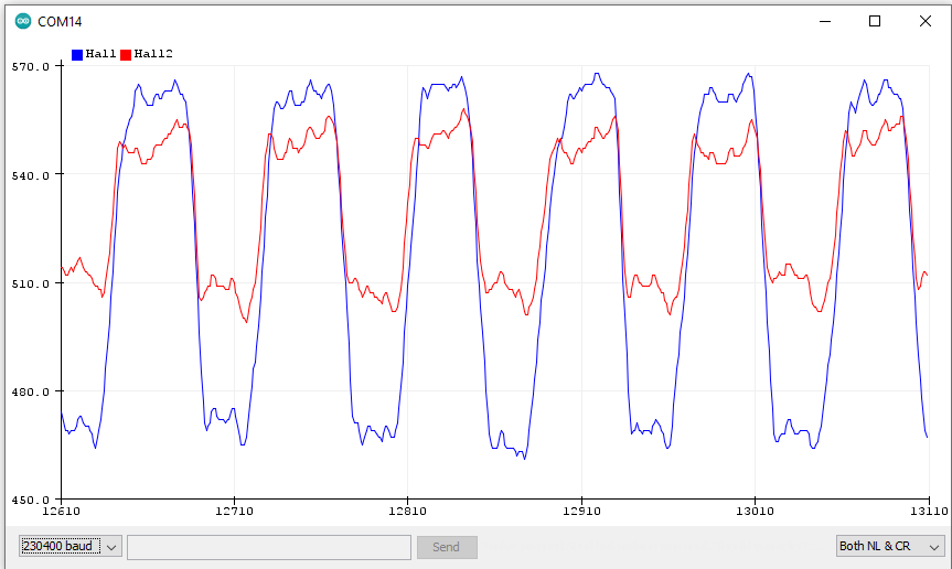
These are the readings from 2 halls.
I get the occasional jump to 900+ on one sensor and it stays there for a bit. Not sure if the data is good enough…

Can only upload one image. More here: Hall Sensors - Album on Imgur
Anybody with more experience that can way in how the data should look?
Are you printing something else to serial, which may be interpreted as Hall sensor data and plotted? I had such effects and the charts look terrible then…
look at the printout with serial monitor to see if there is extra stuff in the feed, yeah. Also I strongly recommend upping the baud rate to like 1 million baud, I haven’t had any problem with that and it reduces complications.
Those spikes do look problematic. I doubt you could simply filter them out. Try to figure out why they’re happening in the first place.
Can you post an image with the X scaling changed so we can see the wave shape and phase difference better? They need to be reasonably sinusoidal, and 90 degrees apart. It looks like they’re in phase right now, but that seems unlikely because the sensors would need to be placed two magnets (51.4 degrees) apart, or one magnet (25.7 degrees) with one sensor facing the opposite direction so they read same polarity from the opposite polarity magnets.
Actually I can’t figure out how I got the 17.14 degree calculation before… now I’m getting 0.5x360/14=12.86 or 1.5x360/14=38.57 degree spacing for one sensor to be centered on a magnet and the other half way between magnets (90 electrical degree difference).
It also looks like the signals will need to be normalized so they have the same min/max range when fed into atan2. Here is another pull request where someone wrote code to do that: Add two linear halls sensor module. by XieMaster · Pull Request #197 · simplefoc/Arduino-FOC · GitHub
I will have a third sensor. Just couldn’t be bothered to connect all three ![]() Don’t know if that makes a difference to your comment about the 2 sensors and atan2. I thought SimpleFOC supported this arrangement out of the box?
Don’t know if that makes a difference to your comment about the 2 sensors and atan2. I thought SimpleFOC supported this arrangement out of the box?
They are mounted like this:
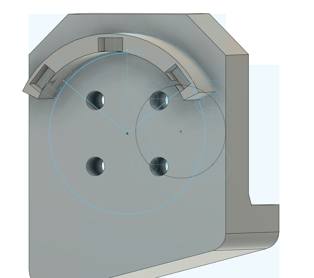
I currently have the left most and the right most slot populated. That’s the graph, that is shown.
I’m reading the sensor data using an Arduino Uno. Not sure how much baud it can take but I will try 256k.
This the whole sketch:
#include <Arduino.h>

void setup() {
  pinMode(A0, INPUT);
  pinMode(A1, INPUT);
  Serial.begin(9600);
}

void loop() {
  int value = analogRead(A0);
  int value2 = analogRead(A1);

  Serial.print("Hall:");
  Serial.print(value);
  Serial.print(",Hall2:");
  Serial.println(value2);
}
It is a 7 pole pair motor.
So the calculation is as follows:
(360 mdeg / (3*pp))
(360 / (3*7)) = 17.1428571429°
And then i multiplied by 3 to get 51,42° since I can’t do 17.14° as one hall is wider than that on my small motor.
SimpleFOC only has support for 3 digital halls, which generate an interrupt when they change state. It would be possible to adapt the code for linear halls, but easier to buy digitals if that’s what you want to do.
Linear halls have the potential to give a higher resolution angle (precise positioning and less jitter at low speed) while also being cheaper and easier (only two sensors, and no filtering capacitors needed), but there’s no code currently included for it, and not many people have tried it. You’ll have to use the code from one of those pull requests.
Your signal plots are not looking good at the moment… more trapezoidal than sunisoudal. You may actually need to move the sensors farther from the motor rather than trying to get stronger signal like I did when I tried it. It looks like they’re saturating. Although it’s odd that they each give different values at their apparent saturation points.
The phase issue also needs figured out. With your current positioning they should be 60 or 120 degrees out of phase (not sure which), but it looks like only a few degrees, if any.
Okay now I’m confused.
I have looked at the wiki and found a hall sensor section. Where the 49E are recommended: Position Sensors | Arduino-FOC
This page also has 49E in the picture at the top: Hall sensors | Arduino-FOC
I thought this was the supported way in SimpleFOC?
I will experiment more with the sensor in the meantime. Not easy… I still have a lot to learn.
But it is strange that the sensor are all in phase. Maybe the calculations are off. I don’t really know. But I can see that all 3 align fully with a magnet at the same time. So there might be something to that.
Well that’s not good… I’ll send a message via the contact link on the web site and get it corrected.
The digital halls I’ve used are US1881 (also known by other similar numbers), but I think SS41F can operate without filtering capacitors, so buy that. I’ve been meaning to try some since I learned of their existence from a hoverboard motor.
I have done some more digging and verified the first formula.
360 / 7 = 51.42°
to get 120° arc:
51.42° / 3 = 17.14°
But to get the multiples since 17.14° is too small you need to take the initial pole pair spacing for 51.42° and multiply that with an integer N and then add the initial 17.14° as describe here: What is the location of the Hall effect sensor in a BLDC motor? - Electrical Engineering Stack Exchange
So this would give: 17.14° + 1 * 51.42° = 68.56° which does seem to make more sense. Then all the multiplying of the 17.14 would do is align it with the magnets. My factor of 3 might be the worst one to choose since it is just the result of 360 / pp. Makes a lot of sense that it all aligns then…
I will try with 68.56° and see if that makes a difference.
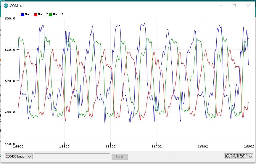
Nice work! Phase looks good now. This should be equivalent to the 60 degree spacing in my post #11, except the sensor_direction will be opposite (no problem).
The waves are looking less saturated now, but still rather rough. But if you replace the sensors with the latching/digital type you should be good to go with the HallSensor class. Although since you don’t have the sensor mount precisely angled relative to the stator, you’ll need to use SinePWM modulation and manually tune the zero angle (command the motor to spin both directions and adjust the zero angle until both top out at the same speed) rather than using Trapezoid120 modulation.
I’m having trouble articulating it, but I think I just had an epiphany regarding this approach ![]() The stator field will still move in steps of 60 electrical degrees, but because you’re energizing all the coils with variable current rather than having one phase deactivated like Trapezoid120, you’re able to rotate the electromagnet field independently of the physical stator arms, creating virtual stator arms wherever you want. Aside from the small effect of cogging torque, this really should work just as well. No more need for physical alignment relative to the stator! I had discovered this experimentally with a motor where I made a mistake machining the sensor/stator mount, but I didn’t really have a clear mental image of what it was doing until now.
The stator field will still move in steps of 60 electrical degrees, but because you’re energizing all the coils with variable current rather than having one phase deactivated like Trapezoid120, you’re able to rotate the electromagnet field independently of the physical stator arms, creating virtual stator arms wherever you want. Aside from the small effect of cogging torque, this really should work just as well. No more need for physical alignment relative to the stator! I had discovered this experimentally with a motor where I made a mistake machining the sensor/stator mount, but I didn’t really have a clear mental image of what it was doing until now.
@Candas1, this should be accounted for in our improved hall sensor auto-calibration attempts.
1 Like
Any idea why the signal levels are so different?
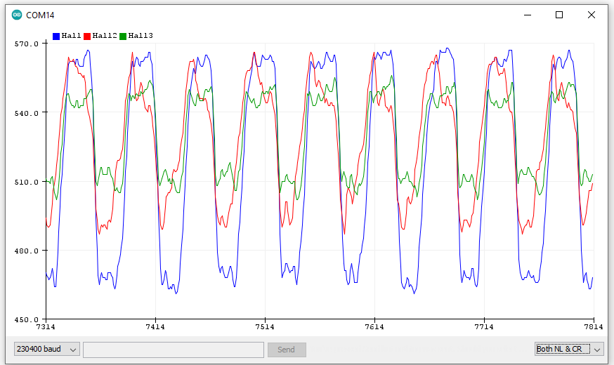
The sensors are not glued in and have a bit of play in the mount. I think this combined with a little roughness in the motor movement is causing them to shift. I have just glued them in and did a new test:
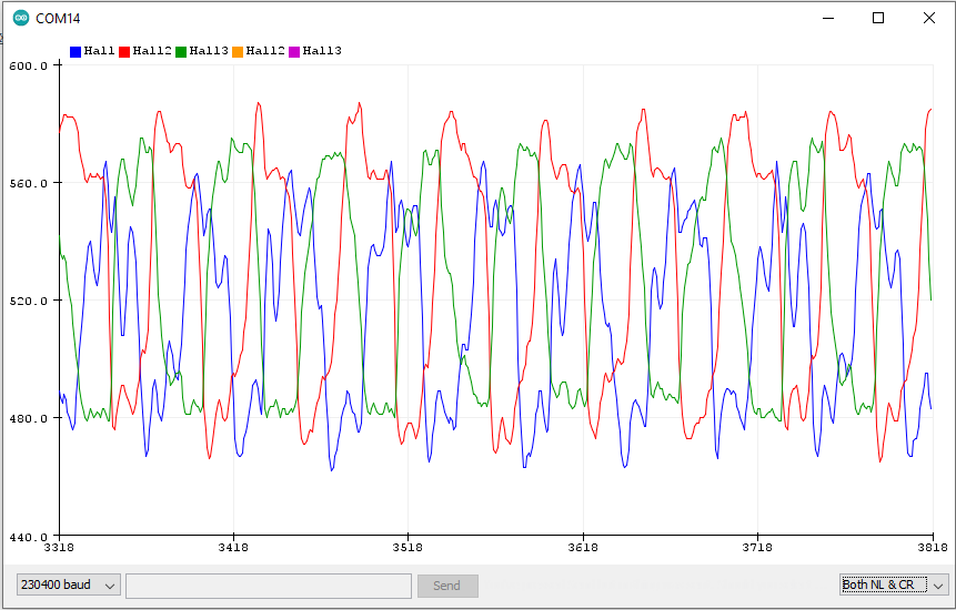
They all still have some difference in the readings but when you just look at one line it’s pretty consistent. The difference between the 3 sensors is probably because of slight variance in the distance to the motor.
If you want to play with the raw data here is a dump: Data package from August 8th. - FileTransfer.io in a poorly formatted csv ![]()
My SS41F arrived today (I really need to find another source. Waiting 1 week every time is annoying :D)
The initial results look promising:
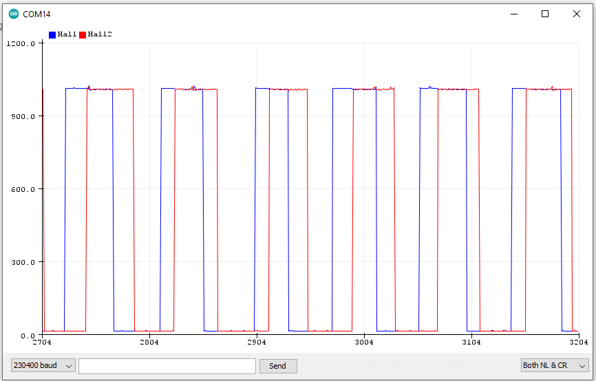
Only 2 halls since the third one keeps falling out of the mount right now.
Need to fix that still…
Before I burn another motor or ESC. Should this sketch work fine?
Not sure how to configure the pullup for the hall sensors? Or are the resistors on the board already? I’m just confusing myself at this point ![]()
#include <SimpleFOC.h>

#define MAGNET_PAIRS 7

// BLDC motor & driver instance
BLDCMotor motor = BLDCMotor(MAGNET_PAIRS);
BLDCDriver6PWM driver = BLDCDriver6PWM(A_PHASE_UH, A_PHASE_UL, A_PHASE_VH, A_PHASE_VL, A_PHASE_WH, A_PHASE_WL);
LowsideCurrentSense currentSense = LowsideCurrentSense(0.003f, -64.0f/7.0f, A_OP1_OUT, A_OP2_OUT, A_OP3_OUT);
HallSensor sensor = HallSensor(A_HALL1, A_HALL2, A_HALL3, MAGNET_PAIRS);

//target variable
float target_velocity = 12;

void doA(){sensor.handleA();}
void doB(){sensor.handleB();}
void doC(){sensor.handleC();}

void setup() {
  sensor.init();
  sensor.enableInterrupts(doA, doB, doC);
  motor.linkSensor(&sensor);

  driver.voltage_power_supply = 14.8;
  driver.voltage_limit = 0.4;
  driver.init();
  motor.linkDriver(&driver);

  currentSense.skip_align = true;
  currentSense.linkDriver(&driver);
  currentSense.init();

  motor.voltage_limit = 0.4; // [V]
  motor.current_limit = 3; // [A]

  motor.controller = MotionControlType::velocity;

  motor.init();
  motor.initFOC();

  Serial.begin(115200);
  Serial.println("Motor ready!");
  _delay(1000);
}

void loop() {
  motor.move(target_velocity);
}
I will still use my battery charger in PSU mode with a 2A limit for initial tests to be extra safe. I even considered getting a vifly short saver but that’s another 3 weeks shipping… ![]()