STM32G431RB ( 64 Pin ) Custom Board

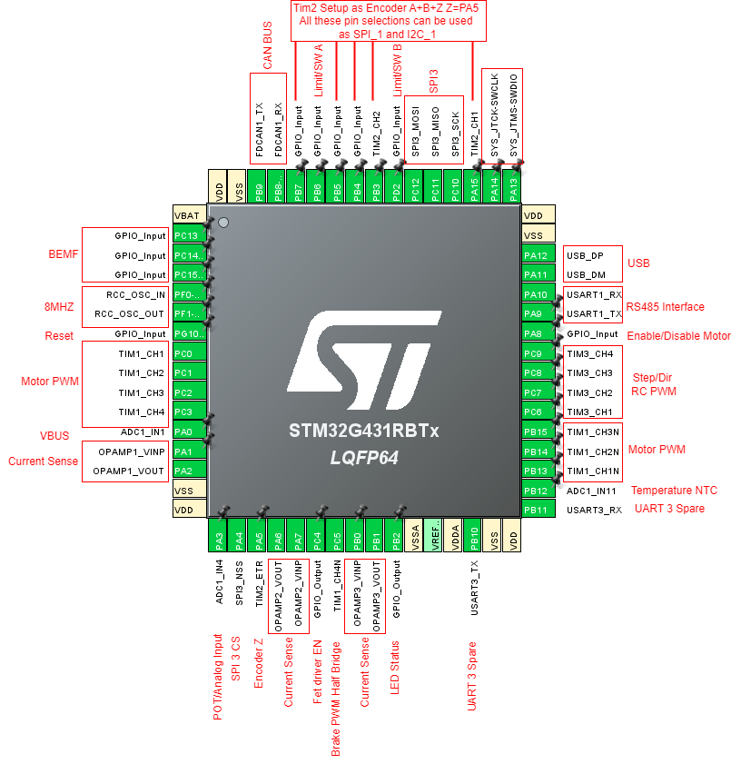
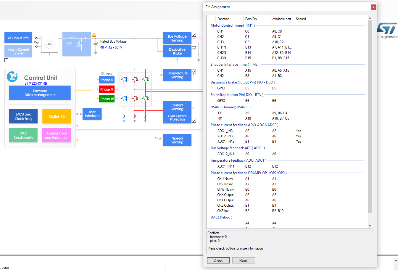
I’m looking at designing a custom board using the 64 pin variant of the G431 which will support up to 80V Input and 30A, something comparable with the ODrive. I will be mainly using 48VDC Motors but would like to try some 80V larger motors. The prototype I may support up to 50v to help with costs. I am trying to figure out a suitable pin configuration. I would like to use the onboard USB but this moves the Tim1 pins to different pins. Also I can’t move the CAN pins and one is shared with the boot select pins. I did read some posts about the 100 pin version and a lot of pins were left un used. How hard is it to get a prototype up and running with Arduino and PlatformIO using generic MCU? I see the RB board is supported in the arduino stm32 core. Here is the layout I have been mucking around with STM32 Cube IDE. I can’t workout how to correctly configure Timer1

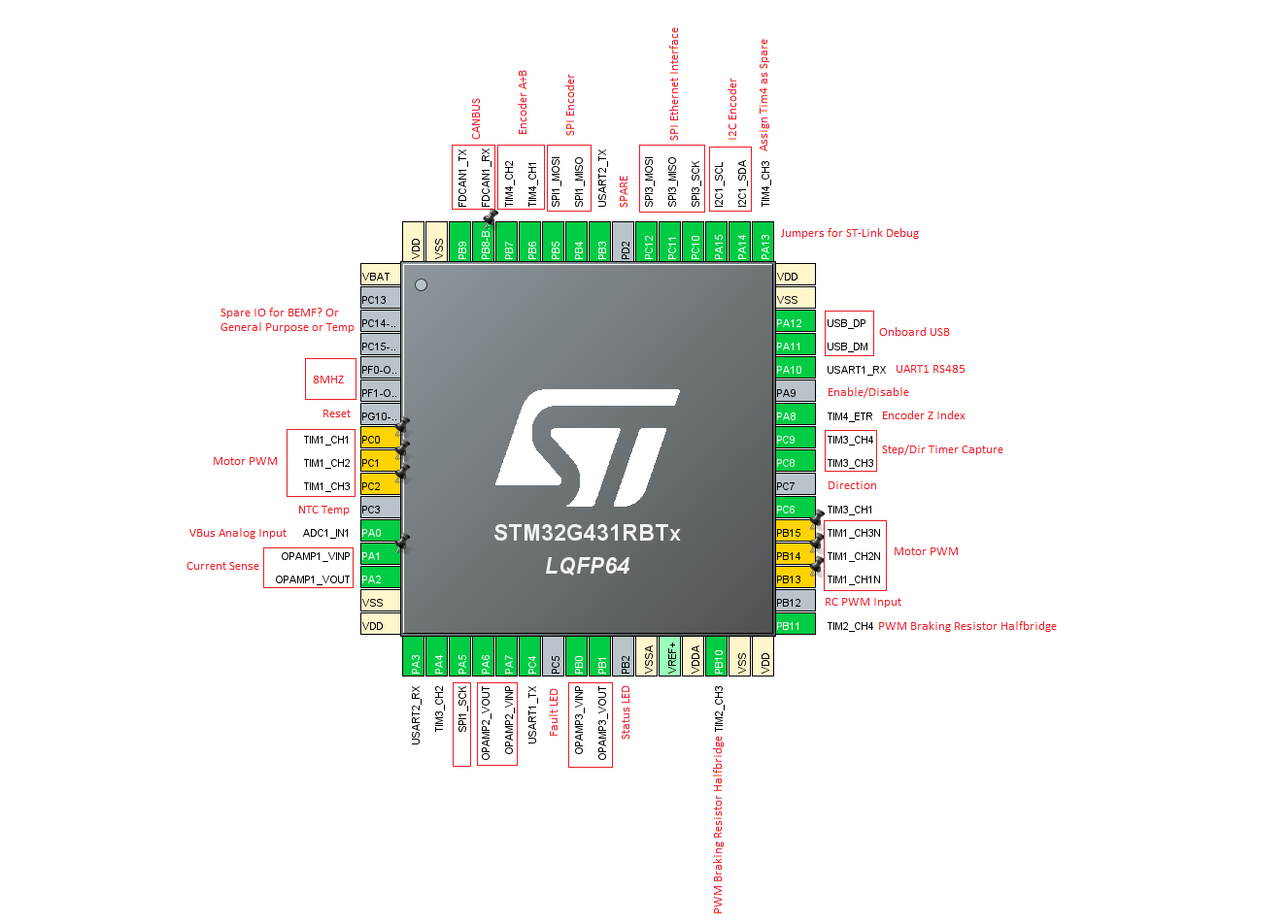
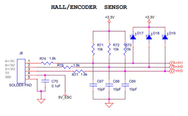
If you have any better pin selections I should use I will change to suit. Is the BEMF detection needed at all or a good to have for future support when simpleFOC supports BEMF? I may move I2C to leave the ST-Link pins free. I did read there is some issues getting the USB to work correctly to upload code? I’m hoping it’s not to much work to get working since there is already arduino support for this MCU

I have updated the IO to better suit simpleFOC and the Encoder Interface, with the 6 pins we can have Timer 2 Encoder A+B and Z Index and also I2C 1 and SPI 1 is available as alternative. I have added the brake PWM to Timer 1 channel 4. Am I missing anything or wrong pins that it won’t work with simpleFOC?

Regarding the internal opamps for current sensing, I based my pinout off the ST Application notes and then I noticed on the B-G431-ESC1 schematics there are 3 pins being used for the current sense. Can I use the 2x pins like in the application notes?

Here is the section for the B-G431-ESC1:

EDIT:
I did some more research using there motor control workbench and custom board setup to check PINs and Opamp Calculator and it looks to setup the same as in the application notes.

With the calculator and using the same value resistors as the B-G431-ESC1 for the opamp feedback, the output voltage for the ADC is quite low. Should I adjust these values? What is the programable gain set to on the B-G431-ESC1, I think this is due to the low readings on the calculator

Maybe something more like this, the default settings.

Nice project!
I don’t know much about big motors like yours but re: setting this all up, it’s pretty straightforward in PIO. Arduino might be more difficult because you might need build flags for some of the things you are talking about later (configuring internal op-amps).
I would recommend to make a big board.h with a ton of defines that just match your .ioc file so that you can keep everything straight.

Have you used the B-G431B-ESC1? You might be able to learn a lot from that for how to use the integrated peripherals of the MCU.

Its not that hard, I can help you once the time comes that you want to prepare to test your new board…

I would use a bit more of the range, personally…

Certainly, you can. The three pin configuration permits some extra options like external filters and feedback. But you can also rely on the internal circuitry.
It will be easy to comment on all this once you have a schematic for your board - then it will be possible to understand the analog part of the circuit in its entirety and give meaningful feedback. Before that everything is very hypothetical. So yes, hypothetically 2 pins will work :slight_smile:

From the point of view of SimpleFOC it isn’t needed and currently isn’t used. But it’s on the roadmap for the future. Again, same thing goes as for the current sensing - we’d have to see a more complete circuit for what you intend to do. It might also be a strategy to design it and layout it but not include it in the v1 of the board? I think you’ll find that for 50V-80V it will be quite complex, involving either isolation or buffers, and therefore also costly for something that isn’t even supported yet.

@VIPQualityPost yes I have used the B-G431B-ESC1, it’s a great board and I have pushed it to the limits, I added braking resistor to it etc also used the Odrive with SimpleFOC etc The B-G431B-ESC1 is just to small to robotic applications. On my board I want to allow use of 12-24vdc Industrial Encoders also. So I will have jumper to select 24vdc tolerant IO so I can also control directly from an Industrial PLC etc

@runger I will start on some schematics in the next few days. As for the BEMF I just wanted to allow it in the future and whether the implementation the B-G431B-ESC1 uses will be correct way when it get’s implemented in simpleFOC

What are your thoughts on running encoder through optocouplers? I will allow jumpers so the I2C and SPI can still be used

I’m just thinking of best method to share the pins for the encoder interface. On the B-G431-ESC1 looks like they are clamping the voltage to 3.3v using diodes and a current limiting resistor on the pins along with 10k pullups. I’m surprised the I2C works with the 1.8k inline and the 10k pullups. I’m thinking of solder jumpers to give access SPI direct access to the pins and possibly the same for the I2C with some 2.2k or 4.7k pullups.

image

I noticed you have two pins reserved for the opAmps (each). But it looks like the B-G431 board has three pins (for each current sense). Positive and Negative connecting to the shunts and the out-pin for ADC . I may be wrong, just to double check.

You’re right - you can feed the output into a comparator input, and you can use external feedback and filters - but you can also leave this out and use the chip’s internal functions for these things. But you may find the gain values offered there unsuitable, or have other reasons not to do it this way.

Basically the OpAmps and comparators are quite versatile and you can use them in many ways. Matt303 links to one of the App-Notes describing it further above.

1 Like

@Matt303: might also want to look at the STSpin32G4 chip, used in projects like Field Stack trials (STSpin32G4)

Same processor as the STM32G431 (same speed), up to 40 GPIOs available, ready to drive gate drivers directly (1A sink/source)

I was hoping to use this processor on the lepton 3.0. I think we should collaborate. If you see my previous posts on the topic, I think our needs are similar, although you are looking for considerably higher currents.

See my last posted thread here Beginning of a proposal for Lepton 3.0 - #19 by Anthony_Douglas on the general idea that I was aiming for.
Basically a general purpose motor driver based on the MCU you are talking about.

I think it is very important to realize that this stuff is not actually that easy. The internet is littered with at least a dozen half done projects and only one or two like VESC that are really done because people realize how much work it is after starting and then don’t continue. The Odrive guys realized how much work it was and decided they couldn’t figure out any other way to get paid except to go close source. The same thing happened with bl_heli.

You definitely need ST_link.

In line with how much work this stuff is, the first physical boards should probably be considered a draft. At least 3 iterations can be expected before it’s really solid even if the community collaborates.

In my experience designing IoT boards, if you are purely operating in the digital domain, usually the second revision is ready for production, in rare cases even the first one.

It’s the analog part that is difficult to get right in few tries, especially when high currents and low noise are needed, like in this case. And where PCB layout makes a difference (unlike purely digital, where for the most part the layout is not as critical).

And, yes, as the joke goes, the last 20% of a project takes the last 80% of effort :slight_smile: Github and Hackaday are a graveyard of half completed projects

1 Like

Hi @Anthony_Douglas I had a read through your post and I think current sensing is defiantly needed. I use it for sensor less homing etc

The BEMF I currently propose is just a thought for future support but I probably won’t add it at this stage.

I think the best option is we come up with a general pin layout like I have done above and a basic schematic that can be altered easily for people doing other custom boards. This also means one general purpose board can be created for SimpleFOC with all the correct pin definitions.

Have a good look at my pin layout and see if anything is missing for your needs and I will try to adjust it and if we are happy with the selection of pins we can start working on some schematics.

Are you using KiCad?

I don’t think a pin payout for custom boards is enough, as you are seeing there is a long road with a lot of details between that point and a working motor driver. As others have also found. Someone has to traverse that road, and the user can’t do it at the last minute. But this is a start.

Will have a look though. I’m using Easy EDA, either is good but it’s integrated with JLPCB so the actual step of sourcing all parts and getting the board made is more tractable. There are a lot of little tiny parts, soldering things manually is not at all practical.

I think things should generally resemble the B-G431b-esc1 board re pin mapping. It appears that your proposal mostly follows that.

Hm, you don’t really get any spare pins do you? I think the main thing is to break as many pins as practical out and connect the ones that need to be connected to the current sense etc. so even the led pin could be broken out, for instance. To 2.54 mm through hole pads, which can use a dupont, molex or 2.54 mm screw terminal. That way the LED can be used as in/out if you wanted to for instance. Anyone who doesn’t need CAN can use those pins for other stuff. etc.

In other words, the first stop is making things programmable and flexible.

We definitely want SPI , I2C, and ST-link, UART broken out, the op amps connected to pads where shunt resistors can go (ideally with the option to omit the shunt resistors, e.g. a through hole near each pad that the resistor would solder to could be used to help put a wire in place instead of the shunt, or maybe we can just say use the pads an a piece of wire).

Might be good to have an area with pull up resistors for i2c, whose traces can be cut if needed, as Runger notes I think he mentioned that was a good way to to i2c pull up resistors. Most people are not using more than one device on the I2C line and an extra set of resistors is I think ok most of the time, so if the terminal device is an as5600 board of the usual type for instance it should still work, they contain 10k ohm pull ups (the experiments with the lepton indicated the lack of pullups was a thing, however that may have been incorrect, it may have been the noise issue on the lepton which the extra pull ups masked, and in any case that one board which I thought maybe didn’t have pull ups was a non-standard as5600 board that is not commonly available).

Well, it’s a good time to be designing G431 based boards. LCSC has them very cheap: Search by "STM32G431C"
If you like the QFN48 format of the STM32G431CBU6 you can get them for less than $1.50

This depends on your design. My personal pain-point is currently around 0603 size. But for most components you can choose the size, and can choose not to make everything 0402 and smaller. Using a bit bigger components greatly increases solderability.

Of course once you have a design you’re happy with and want to produce many, the turnkey assembly makes a lot of sense. But @robca already mentioned the difficulty of designing the analog part - if you can self-assemble a few prototypes a single cheap ($5?) JLC order for PCBs will let you try out dozens of variations of your analog design using different component values/brands/types…

If I may put in a preference for connectors:

Stemma/QT (JST-SH1.0 4 pin) for I2C
6-pin JST-SH1.0 for SPI (like here: Magnetic_Encoders/SPI_pinout.png at master · runger1101001/Magnetic_Encoders · GitHub)
4-pin JST-SH1.0 for UART
ARM-14 header for SWD + Serial

Consider if you need the UART connection. I would instead put it on the SWD (where it is then automatically connected to. the PC via the ST-Link). Or if you want to use 2 extra pins on the MCU consider USB, which can also transport serial streams and is more versatile (e.g. also able to provide power, has shielded connection, additional USB profiles and more).

Use a “solder jumper”. I like to use them “normally closed” so the user only has to cut the trace if he doesn’t want the option (in this case the pull-ups). It’s a zero cost solution and most PCBs have extra space on the back to put the solder jumpers.

I personally would not do it this way. If you want this, then why not use the SimpleFOC shield on the Nucleo64 G431 board? All the pins will already be broken out, plus the Nucleo has a built-in ST-Link.
This approach suggests the board can be used for other things, but in fact it will be 100% busy with motor control.

My opinion is the driver board should focus on the motor control. The interfaces it offers should be used as command inputs for the motor driver, or as interfaces to the required sensor, or as outputs for telemetry. What functions it has, it should offer on-board, and it should not try to also be a general purpose MCU board at the same time. The driver board then anyway interfaces with a controlling MCU or PC, and this other system can worry about the other stuff.

1 Like

nucleo plus shield is way too expensive, though. It’s like $60 usd for the shield plus a nucleo board. it also has poor current capability and is lacking on many other counts compared to what could be provided for $15 usd. IDK how available it is. It was a great start, I don’t want to knock it, but I think it’s high time for a second generation.

Previous estimates for a well designed board with much better features, 6 pin instead of 3 pin (which I gather allows some features such as regenerative braking? Also perhaps finer control over dead time etc.)

Secondly, in any case I think it would be important to at least settle on an exactly nucleo board, as it has become clear there are a lot of features which have to be sorted out on an mcu by mcu basis.

For a one of project I agree the shield and nucleo board makes sense, but I think it warrants a sucessor. I also think it would be advisable to share this idea of using a nucleo board, not an uno, more prominently in the documentation as I think due to the shield design and so forth a lot of people are thinking that an uno can do at least something but it’s really not up to much.

Those BEMF inputs don’t have ADC IN.

Are you planning to support stepper motors (I see 4 PWM timers)?

Maybe you could use TIM1_BKIN as a Enable/Disable Motor (PC13/PB10/PB12, etc)?

Hi @dzid26 I probably won’t use BEMF at this stage, was just for future proofing. The 4th Timer is for another half bridge for a braking resistor. I don’t see why it can’t be used to drive a stepper or 2x DC motors if needed. Why use TIM1_BKIN as enable/disable?

Hi @runger I will take note of preferred connectors and use them. I have just had a massive project come up for work so this has delayed me on this project, so hopefully get something on paper in the next few weeks

2 Likes

TIM1_BKIN can be programmed to “physically” :wink: stop the timers (even if the CPU halts) which is a neat safety feature (emergency stop).