Field Stack trials (STSpin32G4)

Open loop velocity is running. Still tuning parameters. I think we need current sense to get any kind of speed out of steppers. It’s still early in the process, Next step is to calibrate the sensor.

Motor and controller are completely cool.

TODO: zero sensor instead of setting angle offset. The SFOC initFOC gives varying results when determining angle offset.

2 Likes

@Owen_Williams

What kind of speed are you able to get out of steppers. Is the high inductance, 9mH in this case, in the way of achieving higher speeds? Maybe its voltage related as well…

I am using a really crummy low amp typical router PSU in above vid. Hmm… maybe I should give it some juice. I’m ordering some low inductance steppers, to compare.

@Antun_Skuric

Does setting the duty-cycle to 0.00f produce a true ground (HI = LOW and LI = HIGH), or could it be cross conducting in some cases?

Is the sensor using an axial magnet mounted sideways?

Yeah, I had some issues with a UPS employee. He was waving around my package with the Magnets I ordered from DigiKey, but would not hand it out or even let me take out a 8x2.5mm 150C rated magnet. This the 11th I should be able to try out the proper magnets. Those axial ones did the trick for getting the SPI coms to the MT6835 working though. Maybe its ok, yet another small experiment :stuck_out_tongue:

@Valentine when trying closed loop with that magnet I am seeing some weird behavior, like the field is uneven. Or maybe it’s related to calibration.

@runger

I have modified the MT6835 → setZeroFromCurrentPosition() function. This works, but there is a strange quark.

#define MT6835_OP_ZERO  0x50
...

bool MT6835_STM32G4::setZeroFromCurrentPosition(){
    
    digitalWrite(nCS, LOW); // manually take CSN low for SPI_1 transmission
    SPI.transfer(MT6835_OP_ZERO, SPI_CONTINUE); 
    SPI.transfer(0x00, SPI_CONTINUE); 
    if (SPI.transfer(0x00, SPI_LAST) == MT6835_WRITE_ACK){
    digitalWrite(nCS, HIGH); // manually take CSN high between spi transmissions   
    return true; }
    else {digitalWrite(nCS, HIGH); // manually take CSN high between spi transmissions
    return false;}

};
SerialUSB.println("Setting MT6835 Zero Position ->");
  motor.setPhaseVoltage(motor.voltage_sensor_align, 0,  _3PI_2);
  // wait for it to settle
  delay(2000);
  if (sensor.setZeroFromCurrentPosition() == true){
    SerialUSB.println("Zero Position ACK OK!");
  } else {SerialUSB.println("Zero Position ACK failed!");}
  
  delay(1000);
  // Read out latched angle
  for (int i=0;i<3;i++)
{
  readMT6835 = sensor.getCurrentAngle();
  Serial.println(readMT6835, 8);
}

It always zeroes to:

Angle (RAD):   0.00041945

Or in that very close vicinity. If its a issue, we can use that as offset ?

EDIT: Its electrical angle (50 PP)

EDIT2: I see I forgot to pull nCS HIGH. Maybe that was the problem.

With motion_downsample = 3; I am seeing total loop times of;

time per iterasion:   33.5787
time per iterasion:   33.6074
time per iterasion:   33.4000
time per iterasion:   33.4783
time per iterasion:   33.5265

with motion_downsample = 20; it goes a bit down to 31 micros();
These times is including the MT6835 SPI reading.

What units is that? It’s better to give it as iterations/second, that’s easier to compare with past results etc…

33 micros(); should be around 30 Khz loop freq?

I will try to see what effect the hardware encoder interface has on loop frequency.

Edit: doing some math to set this into perspective. If our target rpm for steppers is 1500 rpm then that is (1500/60) 25 rps. Having 50PP that equates to 1250 electrical_rev’s per sek. With the measurements above we should be doing 24 foc-loops per electrical_rev going 1500rpm.

Contemplating hardware encoder setup:

Bookmark timer setup: [Solved] Set alternate function for quadrature encoder pins. - Arduino for STM32 (stm32duino.com)

The timer is 16bit (65,536) ticks, 0 to 65,535. This divides perfectly with 2, so we can cast the lower half to -pi and the upper half to +pi, which is what the CORDIC expects. Actually it just expect a signed 16bit value.

Depending on encoder mode x4, x2 or x1 we then set the MT6835 ABZ resolution.

Maybe it’s better to shift the bits to q1.15. Supposedly one can then do a single CORDIC pull, outputting both sine and cosine in q1.31. I suppose that will output two q1.15 values contained in a uint32_t? Or it can output two q1.31 values for higher precision, not sure exactly how it behaves.

The ‘q15_t’ type is a 16-bit, signed number that represents decimal values ranging from -1.0 to +0.9997. Actual values are -32768 to +32767.

That should speed up the CORDIC

Then there is the joker. Setting up another timer for velocity, which will be yet another speed optimization :black_joker:

There is also the option of going for the 32bit timer in encoder mode?

Edit: The MT6835 ABZ has a max res of 16384. Funny enough 16384 x 4 is 16 bit

Tik tik tik tick wow wow

Ok, registers 0x007 and 0x008 is set to:

ABZ1 ->
11111111
ABZ2 ->
11111100

meaning: ABZ is on, No swap, highest pulse-count.

16 bit encoder output :kissing_cat:

597,1111111111110110,6.2822266
598,1111111111110111,6.2823224
599,1111111111111000,6.2824187
600,1111111111111001,6.2825146
601,1111111111111010,6.2826104
602,1111111111111011,6.2827063
603,1111111111111100,6.2828021
604,1111111111111101,6.2828979
605,1111111111111101,6.2828979
606,1111111111111111,6.2830896
607,0,0.0000000
608,1,0.0000959
609,10,0.0001917
610,11,0.0002876
611,11,0.0002876
612,100,0.0003835
613,100,0.0003835
614,101,0.0004794
615,110,0.0005752
616,111,0.0006711
617,1000,0.0007670

And were down to ;

time per iterasion:   21.0880
time per iterasion:   21.0881
time per iterasion:   21.0879
time per iterasion:   21.0878
time per iterasion:   21.0880
time per iterasion:   21.0881
time per iterasion:   21.0880

Not using the CORDIC. Just reading the timer.

Ladies and gentlemen, we are now in the 47Khz vicinity. Still without Analog readings though. The ADC should ideally run with the DMA.

@runger something noteworthy, remember when I was messing around with the SAM51. I seem to remember, how the loop freq. was tied to the PWM freq. ? This is apparently not the case here

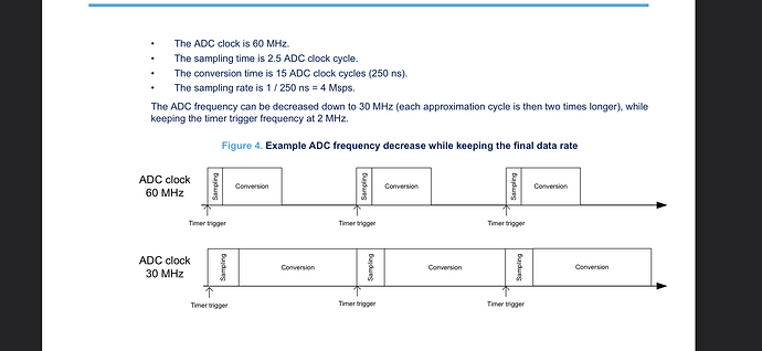
Moving on to the ADC. This application-note from STM describes their advanced use including dual-mode.

https://www.st.com/resource/en/application_note/an3116-stm32s-adc-modes-and-their-applications-stmicroelectronics.pdf

Big shout out to ST for providing the examples in the app-note!

STSW-STM32028 - STM32’s ADC modes and their applications (AN3116) - STMicroelectronics

Lets do this :wink:

Just a quick recap, we have two current sensors, each on different channels (CH1 & CH2). We also have main/cap voltage and temperature (thermistor). Current-sense is naturally priority, but voltage and power-stage temperature is also important. Somewhere I saw, that there exist a internal (MCU) analog temperature reference (also important, but there should be a internal temperature cut-off safety feature as well, TODO: find out more).

Aha… Analog voltage on PA0 can be either CH1 or CH2. Good to know.

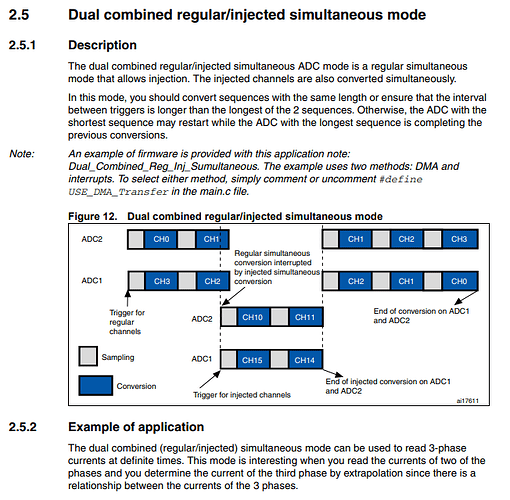
I suppose we are going for “Dual combined regular/injected simultaneous mode” then, since we have two high priority channels and to low priority channels. When the High priority channels are triggered, then sampling or conversion of low priority channels will pause, until Current sense is done.

There is also the “Dual combined: injected simultaneous + interleaved mode”, which may be useful.

What is this “ADC watchdog”?

Since the two phases is independent when in stepper mode, it may not be as crucial to do simulations sampling as is the case when 3phase. But the hardware is also meant for 3phase in some scenarios, so simultaneous is preferred.

Note: All channels are fast ADC channels :nerd_face:

Referring this old thread: STM32 ADC code using stm32duino - developement - SimpleFOC Community

source: STM32CubeG4/stm32g4xx_hal_adc.c at master · STMicroelectronics/STM32CubeG4 (github.com)

I used Dual combined regular/injected simultaneous mode recently for the Hoverboard FOC firmware (STM32F1) so I can probably help if you have questions.

ADC Watchdog can be set with low and high threshold and will trigger an interrupt.
I haven’t tried it yet but I want to use it for overcurrent protection.

Thanks @Candas1

I defaulted to CUBE_MX

Now I have two ADC samples in a DMA transfer to uint32_t

ADC Value  -> 111111110010000011111110101
6,11,0.0002876
ADC Value  -> 111111110010000011111110101
7,11,0.0002876
ADC Value  -> 111111110010000011111110101

Some places they mention a errata regarding some bug:

Example for ADC in multimode with dual DMA? (st.com)

Maybe I should use two DMA channels?

I have 4 active ADC channels. Two on ADC1 and two on ADC2, not sure how they get sampled. I only recently got some bits through, so I need some time to let it all sink in and set up the trigger timer.

This is how it’s configured for regular channels now for Hoverboard firmware
The Ebics FOC code is maybe cleaner.

But for injected ADC you shouldn’t use DMA.

1 Like

This is what I am using in the most recent code but I haven’t published it yet:

Injected ADC for phase currents and regular ADC with DMA for anything else.

I thought the injected type was mainly for low side?

In the stepper scenario, the two phases are independent, so we can’t extrapolate anything about the first from the second…

On the second hand, I want the sampling to happen outside the loop, with no waiting around for conversion.

The amplifiers are quite fast, that may also be a factor. Ina241 are 1.1Mhz.

Maybe if we oversample to 14 bit, the ghost will not be an issue ? I guess 14 bit is a arbitrary number, it does not fit in the byte like 16bit does?

Yes when the timing for current sensing is tight.
Hoverboards have low side current sensing.

I get that is important in low side. While in the stepper scenario, the current should not change faster than we are able to sample. Surely with a 4MSPS or 4MHz ADC we should be able to get a few readings per FOCloop. As long as the ADC is updated before next loop I gues is what matters ?

Is it possible to only oversample the two phases and not the thermistor and voltage divider ?