Made a few improvements.
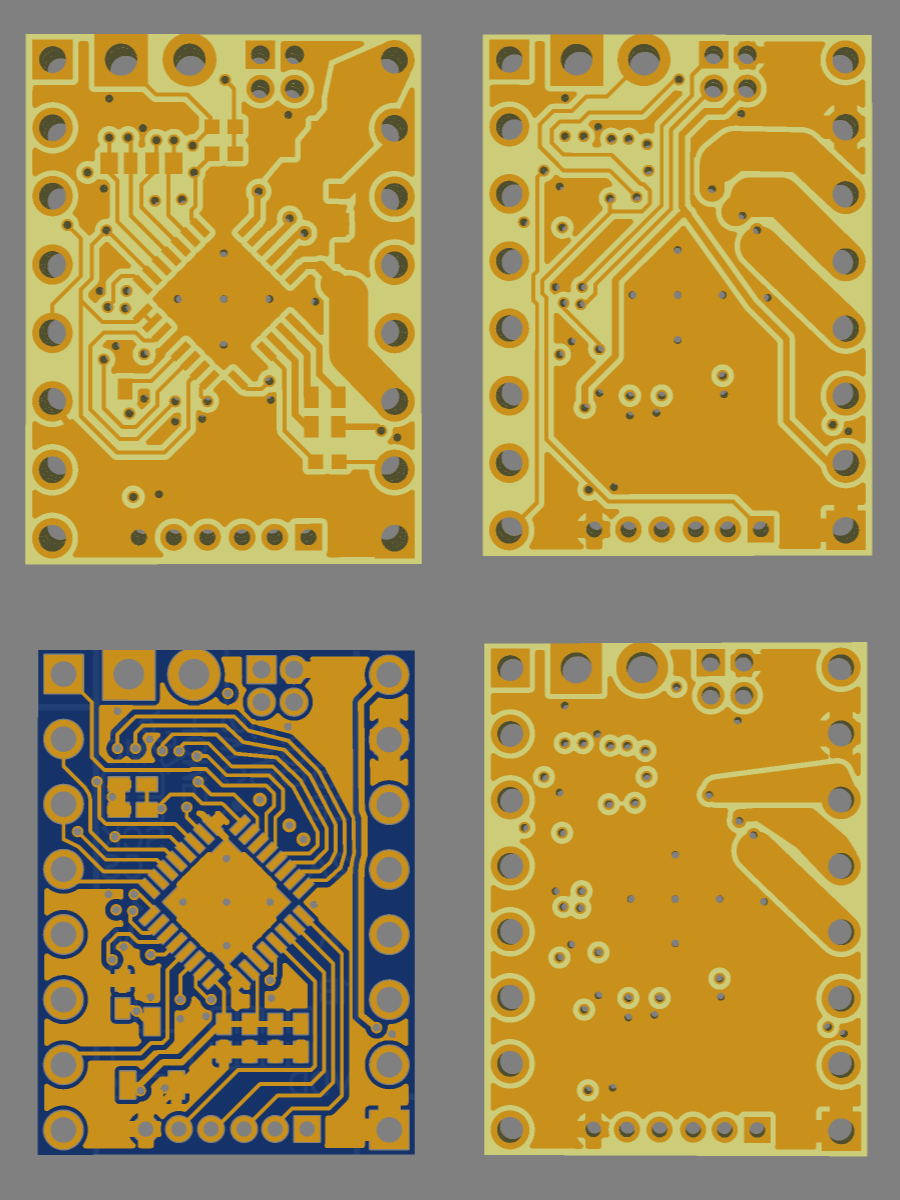
- Added copper for the outputs on Inner1, increasing their conductivity. However the current sense lines lose their ground plane for a few millimeters, so it’s possible this will introduce some noise to the readings. I wrapped a ground trace around the outside of them for a bit of coplanar grounding, but that only really helps the outermost one.
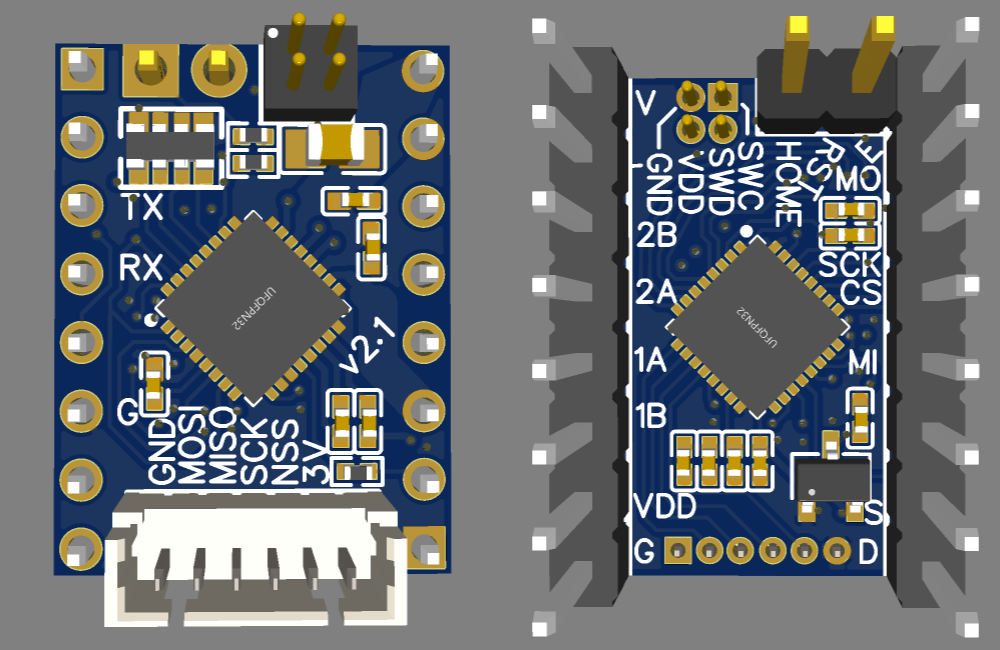
- Connected the last unused stepstick pin to ground so it can be soldered pointing up for UART. It’s only connected on the top layer, so it can be cut if necessary for whatever reason.
- Swapped Inner1 and Inner2, so bottom layer has better grounding. Debatable which is more important, but bottom has more/longer traces than top.
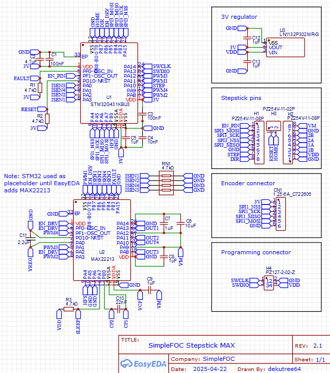
- Shuffled the pin assignments. I realized there was never any need to go to the other side of the chip for TIM1_CH3N. PA12 near the others is TIM4_CH2 and TIM1_CH2N, so we can get some less scrambled channel numbers, plus a new option for 4 non-complementary channels (though not all on the same timer) which might come in handy someday.
Stepper:
2B/OUT1: PA11 TIM1_CH1N
2A/OUT2: PA8 TIM1_CH1
1A/OUT4: PA9 TIM1_CH2
1B/OUT3: PA12 TIM1_CH2N
BLDC:
2B/OUT1: PA11 TIM1_CH4
2A/OUT2: PA8 TIM1_CH1
1A/OUT4: PA9 TIM1_CH2
New option:
PA8 TIM1_CH1
PA9 TIM1_CH2
PA11 TIM1_CH4 or TIM4_CH1
PA12 TIM4_CH2
I think I’ll order 5 un-cut panels of 30 boards each, with a stencil. It’s humorously cheap, only twice the price of 5 single boards without stencil. I have a CNC to V-cut them myself, and this way I can assemble them as needed until such time that they become popular enough to justify ordering assembled boards from JLC.